Recently I needed to calculate the gearbox for a machine I was building. Since humans are lazy by nature, I decided to use a computer to help me.
Unfortunately, a computer can only break down of its own accord, so out of laziness a so-so calculator for calculating gear ratios was created. Calculations are based on WHEEL diameters, not on effective (pitch) diameters. In my practice, this is completely sufficient - the difference in rotation is like the stability of an elephant depending on where the fly lands on it.
The idea of the calculator is to select diameters so that the axle distance in individual gears is the same (this speeds up gear shifting)
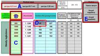
I have shown the individual elements of the calculator in the drawing

Description for the drawing:
- part A - use the buttons to select the width of the belt
- part B - here we enter the revolutions of the driving part (e.g. engine)
- part C - we can enter the revolutions we want to obtain, up to ten items, in ascending order (if we want to get some reasonable results)
- part D - in this cell, by default, the program inserts the smallest diameter of the drive pulley recommended for a given belt. But if necessary, you can manually insert a different value (in mm)
- part E - contains three buttons, using them you can print visible tables or drawings of the pulley assembly (for clarity, the drawings are printed halfway to the symmetry axis) Note! - the drawings are scaled to fill as much of the page as possible, so they are not correspond to real dimensions!
I forgot to add that if any field in the wheel diameter table (blue fields) is highlighted in red, it means that these diameters are not recommended (too small) and do not guarantee correct calculations. Then you need to manually set the first gray field to an appropriately higher value (field D). Such cases will occur if we enter low values in the input rpm field from which we want to obtain high rpm.
Unfortunately, a computer can only break down of its own accord, so out of laziness a so-so calculator for calculating gear ratios was created. Calculations are based on WHEEL diameters, not on effective (pitch) diameters. In my practice, this is completely sufficient - the difference in rotation is like the stability of an elephant depending on where the fly lands on it.
The idea of the calculator is to select diameters so that the axle distance in individual gears is the same (this speeds up gear shifting)
I have shown the individual elements of the calculator in the drawing

Description for the drawing:
- part A - use the buttons to select the width of the belt
- part B - here we enter the revolutions of the driving part (e.g. engine)
- part C - we can enter the revolutions we want to obtain, up to ten items, in ascending order (if we want to get some reasonable results)
- part D - in this cell, by default, the program inserts the smallest diameter of the drive pulley recommended for a given belt. But if necessary, you can manually insert a different value (in mm)
- part E - contains three buttons, using them you can print visible tables or drawings of the pulley assembly (for clarity, the drawings are printed halfway to the symmetry axis) Note! - the drawings are scaled to fill as much of the page as possible, so they are not correspond to real dimensions!
I forgot to add that if any field in the wheel diameter table (blue fields) is highlighted in red, it means that these diameters are not recommended (too small) and do not guarantee correct calculations. Then you need to manually set the first gray field to an appropriately higher value (field D). Such cases will occur if we enter low values in the input rpm field from which we want to obtain high rpm.


