At the very beginning, a few pieces of information so that there are no misunderstandings.
These are not comprehensive belt transmission calculations, but basic calculations that help to choose some parameters of such a transmission.
When calculating and selecting parameters, one should rely on the standards and standard parts !!!
The diameters of the pulleys and the belts are standardized !!!
I recommend studying the "Constructor's Guide" (general purpose belt transmissions with V-belts manufactured by "STOMIL SANOK" SA used in the construction of machines and devices):
http://www.stomilsanok.com.pl/upload_module/segdownload/poradnik_konstruktora_2012_pl.pdf
I do not include standards or links to them for legal reasons. The standards are available in school and university libraries, in the technical departments of companies, they can also be purchased :)
---------
So let's get to the heart of the matter :)
Belt transmission - calculations of pulley diameters and rotational speeds using a spreadsheet (Microsoft Excel, LibreOffice Calc)
(list of attachment files at the end of the post)
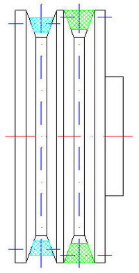
Pulleys and V-belt - illustrative drawing

Belt transmission - calculations of wheel diameters and rotational speeds (MS Excel 2003) .xls
Belt transmission - calculations of wheel diameters and rotational speeds (LO Calc 3.5.0).
I prepared the sheets for my own needs (construction of an electric conical (drill) wood splitter), but maybe they will also be helpful for others :)
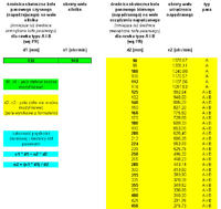
Tab "calculations on table"
- it is enough to enter the values "revolutions of the motor shaft" n1 and "effective diameter of the active (driving) pulley on the motor shaft" d1
- and then select from the table the value "effective diameter of the idler (driven) pulley on the shaft of the driven device" d2 for the value we need "revolutions of the driven device shaft" n2

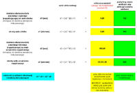
"Calculations on formulas" tab
- it is enough to enter three known values to calculate the fourth value

ATTENTION: Since these are mathematical calculations, appropriate normalized values for pulleys and V-belts should be selected from the standards !!!
Dependencerotational speed and diameter of pulleys:
n1 * d1 = n2 * d2
Motor shaft rotation:
n1 [rpm] = (n2 * d2) / d1
Driven device shaft rotation:
n2 [rpm] = (n1 * d1) / d2
Effective diameter of the active (driving) pulley on the motor shaft:
d1 [mm] = (n2 * d2) / n1
Effective diameter of the idler (driven) pulley on the shaft of the driven device:
d2 [mm] = (n1 * d1) / n2
ATTENTION: The effective diameters of pulleys are the diameters at which the load is transferred for standard V-belts and for which the rotational speeds of the driven devices are calculated. These are not the outer diameters of the pulleys, but smaller diameters than them !!!
Pulley and V-belt - pictorial drawing
For comparison, the location in the groove on the pulley of type A and B belts. Use the same type of belts, e.g. for a 2-groove pulley: 2 belts B or 2 belts A.

---------
A few comments from myself !!!
- effective diameters of pulleys are mathematically calculated values, so it is necessary to select from the standards, the normalized effective diameters (closest to us) of pulleys and the width of the raceways for V-belts
- V-belts (dimensions) are selected from the standards
- outer diameters of pulleys should be calculated (or selected) so that the V-belts do not fall from the pulleys (visible in the attached drawings, including "Pulley and V-belt - reference drawing")
- the outer diameters of the pulleys (bases) for the V-belt should be calculated (or selected) so that the V-belts rest with their own side walls on the side walls of the raceway under the V-belts on the pulleys, there should be play under the belts (visible in the attached drawings, m .in. "Pulley and V-belt - reference drawing")
- pulley widths should be calculated (or selected) so that the V-belts are not too close to each other and do not fall off the pulleys
- the angle of contact of the pulley by the V-belt depends on the effective diameter and must be in the appropriate range (information included in the standard) so that the belt does not slip, and there cannot be a large disproportion between the diameters of the pulleys - this is information for those who will choose second pulley to the one already owned (reducing or increasing the speed)
---------
An example for my motor shaft pulley and A (13) and B (17) V-belts.
Data:
- Engine revolutions: n1 = 940 [rpm]
- Effective diameter of the active (driving) pulley on the motor shaft: d1 = 132 [mm]
(Outer diameter of the driving pulley on the motor shaft: d1z = 140 [mm])
- Pulley with two V-belts type B (17). For stubborn, you can also use two A-type belts (13).
(view of both belts in the overview drawing)
- Required revolutions of the driven device shaft: n2 = 650 [rpm]
- The axial distance of the shafts is adjusted by moving the motor in the guides.
Wanted size:
- Effective diameter of the idler pulley (driven) on the shaft of the driven device: d2 =? [mm]
The value calculated from the formula d2 = (n1 * d1) / n2 is: d2 = 190.89 [mm]
As the rotations of the driven device shaft in my case do not have to be that exact, I choose from the standard the closest value of the effective diameter of the pulley: d2 = 190 [mm]. Outer diameter of the pulley: d2z = 200 [mm].
Ds - effective diameter of the pulley (selected from the standards, after previous calculation)
Dz - outer diameter of the pulley
Dp - outer diameter of the pulley (base) for the V-belt
Dw - inner diameter of the pulley (per shaft)
L - pulley width
Attached files:
Pulley Dz140 Dp110 Dw38 L50 Ds125 Ds132 (V-belt type A13 B17) .dwg
Pulley Dz140 Dp110 Dw38 L50 Ds125 Ds132 (V-belt type A13 B17) .pdf
---------
The attachment "Przekladnia_pasowa_obliczenia_by_wave.zip" contains the following files:
Belt transmission - calculations - description.txt
Pulleys and V-belt - illustrative drawing.dwg
Pulleys and V-belt - drawing pogladowy.jpg
Belt transmission - calculations on the table.jpg
Belt transmission - calculations using formulas.jpg
Pulley and V-belt - drawing pogladowy.jpg
Belt transmission - calculations of wheel diameters and rotational speeds (MS Excel 2003) .xls
Belt transmission - calculations of wheel diameters and rotational speeds (LO Calc 3.5.0).
Pulley Dz140 Dp110 Dw38 L50 Ds125 Ds132 (V-belt type A13 B17) .dwg
Pulley Dz140 Dp110 Dw38 L50 Ds125 Ds132 (V-belt type A13 B17) .pdf
[DWG drawings (R2000-2002) made in DraftSight V1R3.2]
---------
PS. If anyone noticed any errors or inaccuracies, please provide an appropriate (constructive) comment.
PPS. If the department is inadequate, I ask the Moderator to be transferred to the appropriate one.
---------
EDITION:
2013-09-10, 22:45
- added drawing "Pulleys and V-belt - reference drawing"
- updated list and files attached
EDITION:
2013-09-13, 18:35
- updated sheet, description, and files attached in connection with the comments below
These are not comprehensive belt transmission calculations, but basic calculations that help to choose some parameters of such a transmission.
When calculating and selecting parameters, one should rely on the standards and standard parts !!!
The diameters of the pulleys and the belts are standardized !!!
I recommend studying the "Constructor's Guide" (general purpose belt transmissions with V-belts manufactured by "STOMIL SANOK" SA used in the construction of machines and devices):
http://www.stomilsanok.com.pl/upload_module/segdownload/poradnik_konstruktora_2012_pl.pdf
I do not include standards or links to them for legal reasons. The standards are available in school and university libraries, in the technical departments of companies, they can also be purchased :)
---------
So let's get to the heart of the matter :)
Belt transmission - calculations of pulley diameters and rotational speeds using a spreadsheet (Microsoft Excel, LibreOffice Calc)
(list of attachment files at the end of the post)
Pulleys and V-belt - illustrative drawing

Belt transmission - calculations of wheel diameters and rotational speeds (MS Excel 2003) .xls
Belt transmission - calculations of wheel diameters and rotational speeds (LO Calc 3.5.0).
I prepared the sheets for my own needs (construction of an electric conical (drill) wood splitter), but maybe they will also be helpful for others :)
Tab "calculations on table"
- it is enough to enter the values "revolutions of the motor shaft" n1 and "effective diameter of the active (driving) pulley on the motor shaft" d1
- and then select from the table the value "effective diameter of the idler (driven) pulley on the shaft of the driven device" d2 for the value we need "revolutions of the driven device shaft" n2

"Calculations on formulas" tab
- it is enough to enter three known values to calculate the fourth value

ATTENTION: Since these are mathematical calculations, appropriate normalized values for pulleys and V-belts should be selected from the standards !!!
Dependencerotational speed and diameter of pulleys:
n1 * d1 = n2 * d2
Motor shaft rotation:
n1 [rpm] = (n2 * d2) / d1
Driven device shaft rotation:
n2 [rpm] = (n1 * d1) / d2
Effective diameter of the active (driving) pulley on the motor shaft:
d1 [mm] = (n2 * d2) / n1
Effective diameter of the idler (driven) pulley on the shaft of the driven device:
d2 [mm] = (n1 * d1) / n2
ATTENTION: The effective diameters of pulleys are the diameters at which the load is transferred for standard V-belts and for which the rotational speeds of the driven devices are calculated. These are not the outer diameters of the pulleys, but smaller diameters than them !!!
Pulley and V-belt - pictorial drawing
For comparison, the location in the groove on the pulley of type A and B belts. Use the same type of belts, e.g. for a 2-groove pulley: 2 belts B or 2 belts A.

---------
A few comments from myself !!!
- effective diameters of pulleys are mathematically calculated values, so it is necessary to select from the standards, the normalized effective diameters (closest to us) of pulleys and the width of the raceways for V-belts
- V-belts (dimensions) are selected from the standards
- outer diameters of pulleys should be calculated (or selected) so that the V-belts do not fall from the pulleys (visible in the attached drawings, including "Pulley and V-belt - reference drawing")
- the outer diameters of the pulleys (bases) for the V-belt should be calculated (or selected) so that the V-belts rest with their own side walls on the side walls of the raceway under the V-belts on the pulleys, there should be play under the belts (visible in the attached drawings, m .in. "Pulley and V-belt - reference drawing")
- pulley widths should be calculated (or selected) so that the V-belts are not too close to each other and do not fall off the pulleys
- the angle of contact of the pulley by the V-belt depends on the effective diameter and must be in the appropriate range (information included in the standard) so that the belt does not slip, and there cannot be a large disproportion between the diameters of the pulleys - this is information for those who will choose second pulley to the one already owned (reducing or increasing the speed)
---------
An example for my motor shaft pulley and A (13) and B (17) V-belts.
Data:
- Engine revolutions: n1 = 940 [rpm]
- Effective diameter of the active (driving) pulley on the motor shaft: d1 = 132 [mm]
(Outer diameter of the driving pulley on the motor shaft: d1z = 140 [mm])
- Pulley with two V-belts type B (17). For stubborn, you can also use two A-type belts (13).
(view of both belts in the overview drawing)
- Required revolutions of the driven device shaft: n2 = 650 [rpm]
- The axial distance of the shafts is adjusted by moving the motor in the guides.
Wanted size:
- Effective diameter of the idler pulley (driven) on the shaft of the driven device: d2 =? [mm]
The value calculated from the formula d2 = (n1 * d1) / n2 is: d2 = 190.89 [mm]
As the rotations of the driven device shaft in my case do not have to be that exact, I choose from the standard the closest value of the effective diameter of the pulley: d2 = 190 [mm]. Outer diameter of the pulley: d2z = 200 [mm].
Ds - effective diameter of the pulley (selected from the standards, after previous calculation)
Dz - outer diameter of the pulley
Dp - outer diameter of the pulley (base) for the V-belt
Dw - inner diameter of the pulley (per shaft)
L - pulley width
Attached files:
Pulley Dz140 Dp110 Dw38 L50 Ds125 Ds132 (V-belt type A13 B17) .dwg
Pulley Dz140 Dp110 Dw38 L50 Ds125 Ds132 (V-belt type A13 B17) .pdf
---------
The attachment "Przekladnia_pasowa_obliczenia_by_wave.zip" contains the following files:
Belt transmission - calculations - description.txt
Pulleys and V-belt - illustrative drawing.dwg
Pulleys and V-belt - drawing pogladowy.jpg
Belt transmission - calculations on the table.jpg
Belt transmission - calculations using formulas.jpg
Pulley and V-belt - drawing pogladowy.jpg
Belt transmission - calculations of wheel diameters and rotational speeds (MS Excel 2003) .xls
Belt transmission - calculations of wheel diameters and rotational speeds (LO Calc 3.5.0).
Pulley Dz140 Dp110 Dw38 L50 Ds125 Ds132 (V-belt type A13 B17) .dwg
Pulley Dz140 Dp110 Dw38 L50 Ds125 Ds132 (V-belt type A13 B17) .pdf
[DWG drawings (R2000-2002) made in DraftSight V1R3.2]
---------
PS. If anyone noticed any errors or inaccuracies, please provide an appropriate (constructive) comment.
PPS. If the department is inadequate, I ask the Moderator to be transferred to the appropriate one.
---------
EDITION:
2013-09-10, 22:45
- added drawing "Pulleys and V-belt - reference drawing"
- updated list and files attached
EDITION:
2013-09-13, 18:35
- updated sheet, description, and files attached in connection with the comments below


