logo elektroda
logo elektroda
X
logo elektroda
ADVERTISEMENT
Treść została przetłumaczona polish » english Zobacz oryginalną wersję tematu
  • DIY metal bench lathe
    I was wondering if this design fits in this forum, but I can see that they were already similar, so it will be a bit of a change in this section.
    Often I was faced with the problem of rolling a shaft (bushings, washers), and anyone who made extra money using the method: a drill mounted in a vice and a file or an angle grinder knows what the "torture path" is, not to mention the limitations of such a method.
    Honestly, I initially wanted to buy a table lathe (ie TSB16), but practically all of them would be - as agreed, all of them were at the other end of Poland, and if it gets closer, the price is unacceptable.
    So I decided to build from scratch, as is well known - you need a lathe to build a lathe but in my case this is not the case, for the construction I used only the hand tools available in almost every workshop.
    Initially, I planned to make the spindle itself with a lathe chuck, so that the material could be processed with a file or grinder, then I tried to use a cross vise (which I had) as a support, the result - a failure.
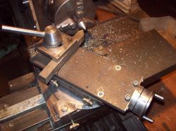
    Finally, I made a bed and a support from scratch, and then I could add new elements on it: gear, feed, tailstock.

    DESCRIPTION:
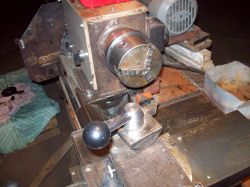
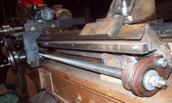
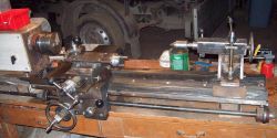
    Spindle - shaft on 2 tapered roller bearings, unfortunately not a through hole (I had one), but inside a 250mm fi25 hole.
    Drive: 3-phase 0.55kW motor powered by an inverter and a single-stage gear with a ratio of approx. 1 / 2.6.
    Bed - angle 120.
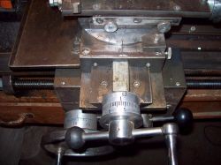
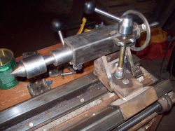
    Lead screw - Tr20x4, cross slide and tailstock - Tr14x4 left-handed, tool sled - Tr12x3.
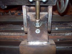
    The bolts of the cross slide and the carriage are supported on both sides by thrust ball bearings, the lead screw from the right has 2 tapered bearings to eliminate the longitudinal play.
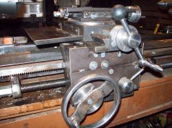
    Longitudinal support - on the crank gear 17z to 34z and together with it 17z with a toothed rack module 1.5, which results in: 1 turn of the handle = 40.055mm.
    The rest in the photo:

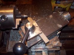
    DIY metal bench lathe DIY metal bench lathe DIY metal bench lathe DIY metal bench lathe DIY metal bench lathe DIY metal bench lathe DIY metal bench lathe

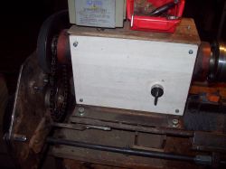
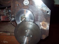
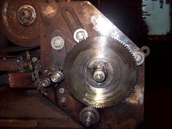
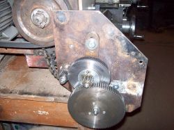
    Here the guitar, gear spindle-intermediate shaft 1/2 chain, then toothed gear: two-stage for feed, and one-stage for threads (all pitches of metric threads can be obtained with one gear), for the 3rd photo setting for a pitch of 1 mm 14z / 28z plus the switch, i.e. left-hand thread in this case.
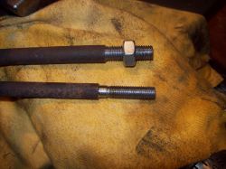
    In the last photo, the larger threads are a typical M10, and the smaller one is M8x1 left.
    DIY metal bench lathe DIY metal bench lathe DIY metal bench lathe DIY metal bench lathe

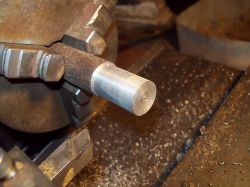
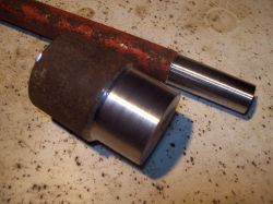
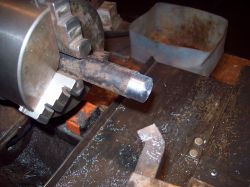
    Rod fi 20 knife with plate and HSS
    DIY metal bench lathe DIY metal bench lathe

    I know that it cannot be compared to the factory design, but not too large elements can be successfully re-threaded, the feeds are two (replacement of the gear on the intermediate shaft) with the diameter of the material, say fi 25 - max. thickness per one pass is about 0.6..0.7mm - with a feed rate of 0.05mm / rev.
    Maybe someone has built similar devices and will share suggestions on what can be improved - I'll be happy to hear.

    Cool? Ranking DIY
    About Author
    azxxc
    Level 17  
    Offline 
    azxxc wrote 148 posts with rating 230, helped 20 times. Live in city Skalbmierz. Been with us since 2007 year.
  • ADVERTISEMENT
  • #2 16905591
    soniak2
    Level 21  
    Hello, a very nice project.
    What are the gears of the guitar taken from?

    Now, if you have a lathe, you can make a better spindle drive wheel hub, because the current assembly does not look the strongest.

    I see that the bed is not ground, how did you keep the angle of the angle?
    If you have external jaws for the chuck, this lathe will be very practical.

    I like
    Regards
  • #3 16905701
    azxxc
    Level 17  
    In the guitar, as well as in the support, standard 1.5 module gears (only the first stage of the feed, module 1) are available in online stores or Allegro.
    Contrary to appearances, the pulley holds up perfectly, but this is how I intend to make some extra (maybe aluminum) so that there is a gear ratio of 1 / 2.9 revolutions = revolutions set on the inverter x10 (e.g. 50Hz = 500rpm)

    Not an unpolished bed, anyway, it would not make sense - only manual grinding, scraping, lapping.
    It is obvious that the accuracy of 0.01mm will not be achieved here

    This is a set of jaws, the thickest shaft that was turned was some 45 and it was quite hard material (probably from the beetle shaft), you had to collect 0.2, 0.3mm
  • #4 16905703
    jalop
    Level 24  
    Milled support sled, did you get it?
  • #5 16905710
    strikexp
    Level 27  
    A piece of good work, especially since it was made without the use of another lathe. Only a friend probably made a mistake in the order of magnitude and wrote that the spindle bore was 250mm :D
    The lack of a through-hole is even an advantage as the machine is stiffer. Well, this is more about machines made professionally.

    I would like to add that when you make your own lathe, you can make a stable spindle at a high height.
    I, for example, bought a slightly damaged 200mm lathe chuck for about 250 PLN. Cattle such that I carry them with the tongue hanging out. But, unfortunately, I do not have the opportunity to use it because a lathe of this size costs a lot and I only thread holes in it.

    My friend has a clearance of 25 mm, which is more than 21 mm in the most popular nutool in Poland:
    https://www.cnc.info.pl/pics/8d93597786f5.jpg
    https://i.ytimg.com/vi/z5eLt4LYon8/maxresdefault.jpg

    Unfortunately, the lathes vibrate from any imbalances and on such a machine the shaft will not touch with an accuracy of 0.1 mm. And this is a lot of play, for example in the bearing.

    @jalop
    The sled is made by twisting 3 flat bars, one plain and two with the edges cut at an angle. Then you can sand it evenly by pressing some abrasive.
  • #6 16905757
    azxxc
    Level 17  
    Quote:
    Milled support sled, did you get it?


    As I wrote, no machine tools were used and, perhaps anticipating the next question - I did not believe it either, but I assure you - it is possible to make guides without a milling machine once, after all, someone made the first lathe or milling machine the accuracy is not the same as with a milling machine but incomparably more accurate than the cross vices available on the Allegro.

    The method in the video below shows how, more or less (additionally scraping and rubbing the valve with paste):
    https://www.youtube.com/watch?v=ACw-eNJ61xg&t=2s

    Yes you are right 0.1 mm I think real accuracy, you can roll under the bearing, you just need to be inventive :D

    When I wrote 250mm, I meant the depth of the hole (hollow shaft on one side) if necessary, it will become a morse taper, probably 3.
  • #7 16905813
    Teres5
    Level 19  
    Cool design. Guitar shift wheels can be purchased. And the horse, knife holder, handle can also be bought? All in all, however, access to a milling machine would be desirable.
  • ADVERTISEMENT
  • #8 16905999
    jalop
    Level 24  
    Milling on the video from the link is quite practical, cool at eye level.

    I like your design. If I can ask you for a video of the rolling, it will show us a lot.
    Do you have any drawings with dimensions? Someone will probably want to look at their own construction here.
  • #9 16906019
    robokop
    VIP Meritorious for electroda.pl
    I will say that art for art - a steel, flexible bed does not provide any stiffness in fact. The cost of implementation certainly exceeded the value of even TSB16, with a fraction of the functionality of that. No possibility to twist the tool slide or move the tailstock = no possibility to turn the cones.
  • #10 16906021
    AdamG123
    Level 16  
    Congratulations on your patience, it's a really good job for an amateur lathe.
    Write down how you made "circles" pointers to measure. You punched or milled the numbers.
  • #11 16906222
    strikexp
    Level 27  
    jalop wrote:
    Milling on the video from the link is quite practical, cool at eye level.


    Not cool at all, because such a thin shield can break and ricochet in the face. Generally, these are sick ideas, because grinding is great (that's what it is called), but with a thick disc, e.g. 10mm, called a grinding stone.
    I bought the cheapest bench grinder with a double stone for about PLN 200. And I will say that she did more work than the ZX7016 drilling and milling machine for PLN 2,000 + PLN 1,000 accessories.
    A stone grinder is a brilliant tool. Especially when you make it yourself from a decent roller.

    Teres5 wrote:
    Cool design. Guitar shift wheels can be purchased. And the horse, knife holder, handle can also be bought? All in all, however, access to a milling machine would be desirable.


    You can buy wheels, but I don't know if you can make a thread. You won't buy a horse very much, at least not cheap. The knife holder is in normal sale because it dents quickly, but the small one costs PLN 150.
    Generally a mill is not accurate unless large and new / overhauled. These are the costs that you can buy at least 3 new lathes.

    In general, in my experience and purchases, a lathe is better to buy. Used for renovation, you can get for PLN 1,500, a new one to be improved, but a specific one (the one from my previous post) for just over PLN 4,000.
    In the latter case, it is a semi-professional machine in which the self-made toy is just a funny toy.
    In lathes, there are quite small forces and therefore they are machines relatively cheap in terms of their capabilities.
    However, with milling machines it is not so colorful anymore and here, in my opinion, it is worth trying something yourself. As if the author of the lathe wanted to go further and make a horizontal milling machine. I would love to see the construction myself. Even if it was inaccurate, it would be great for roughing.
  • #12 16906446
    jalop
    Level 24  
    strikexp wrote:
    jalop wrote:
    Milling on the video from the link is quite practical, cool at eye level.


    Not cool at all, because such a thin shield can break and ricochet in the face. In general, these are sick ideas, because grinding is great (that's what it is called) but a thick disc, e.g. 10mm, called a grinding stone


    It was a sarcasm. Sick, little to say.
  • #13 16906506
    karol75
    Level 16  
    azxxc wrote:

    Not an unpolished bed, anyway, it would not make sense - only manual grinding, scraping, lapping.
    It is obvious that the accuracy of 0.01mm will not be achieved here

    Crap, scraping with a good gauge can be more thorough than grinding.
    It's all a matter of time and skill. In this case, in addition, the stiffness of the bed.
    I'm just worried about wiping the bed, is it steel not cast iron? Additionally, remember that all welds bend the metal and it is better to twist (additionally glue and spring washers) than welding. From what I can see, did you use thick sheet metal? It was better to lay it flat and swallow it and support it well (you can achieve better linearity in relation to the spindle axis).
    And on a lathe made in this way, you can also mount the bearing (grinding / scraping), but it's fun.
    For amateurs, absolutely.
    To the malcontents, he doesn't want to bore the shafts for a car or a helicopter, but to "scratch" himself, or grind something on the revs, and he is absolutely great. Of the new Chinese, the best semi-finished products are LD550 (nutool 550), etc.
    As for the lathes, which can be bought up to 3,000 in addition to new ones, are wrecks for major overhaul, having no knowledge and skills (or machines), they are just scrap heaps.
    Due to the above, an amateur without specialist knowledge and tools (measuring several hundred to several thousand zlotys) will not do anything.
    There is also the question of weight, large lathes weigh around 1000 kg. And they have several KW engines. The question is whether an amateur has a place for such a cow and whether he can afford high power consumption (I omit adapting the installation to such consumption).
  • ADVERTISEMENT
  • #14 16906799
    wada

    VIP Meritorious for electroda.pl
    Looking at your TSB16 and your something - I admire it - a bottom bracket like in the TSB16 - and the rest with a pinch of salt similar.
  • #15 16907027
    Anonymous
    Level 1  
  • #16 16907190
    azxxc
    Level 17  
    Quote:
    No possibility to twist the tool slide or move the tailstock = no possibility to turn the cones.

    Roll the cones like you can't - how you can :D here 60 °
    DIY metal bench lathe DIY metal bench lathe DIY metal bench lathe

    someone asked about the discs, - cast and extruded aluminum discs so that they do not rotate by themselves, standard solution - on the inside a spring and a ball from the bearing, numbers stamped with a numerator, and the lines, after mounting in the holder, cut with a properly set knife and a bumper on the bed.

    There is a bit of a problem with the video, I do not have a webcam and the camera looks bad.


    DIY metal bench lathe

    For now, the inverter must remain as it is (can be moved to another place)
    Quote:
    At idle speed, the fan will work inefficiently, which may cause the engine to burn out, especially if it is an older engine. So, foreign cooling would be nice.

    I am well aware of this, I even have a small motor with a fan that was to serve as additional cooling, but with this work that I do in practice, it turned out to be completely unnecessary, and a thermistor mounted on the motor can be connected to the inverter.
  • #17 16907418
    strikexp
    Level 27  
    I recommend tossing the rods into vinegar for a few hours before processing. The rust is quite hard and destroys knives, not to mention the powdered one makes a mess on the lathe.
  • #18 16907605
    jalop
    Level 24  
    The only thing I can fault is a badly mounted item at the end of the video.
    The post screws, are they the usual M8? Why allen heads?
  • #19 16907736
    azxxc
    Level 17  
    Such an ordinary M8 and for which hexagonal ones - the most convenient for me, you will not buy the original for a post with square heads just like that.

    As for the attachment of the last shaft - only for making a video, but you are right, you should not do this, if only in order not to get into bad habits that sooner or later like to take revenge

    It is strange that no one noticed the lack of a handle cover and a safety switch - it is planned and the switch (mushroom) was even bought.
  • #20 16907773
    jalop
    Level 24  
    With the Allen ones the head is quickly damaged.
    You already have a lathe, now you will cut such a "square" screw (:

    Have you measured the clock on the handle? I am asking out of curiosity what you managed to get.
    As for security, actually do something
  • #21 16907917
    Anonymous
    Level 1  
  • #22 16908009
    kiss39
    Level 39  
    Hello.

    Collect the best solutions. I think that it is worth developing the project of "POLISH" "Modern" Precision Lathes (Mini Lathes) for Metal (as TSA / TSB-16 used to be), because there are no such products on the POLISH market, apart from Made in China products, etc.

    Regards and I keep my thumbs up.
  • ADVERTISEMENT
  • #23 16908783
    Anonymous
    Anonymous  
  • #24 16909572
    E8600
    Level 41  
    The author did a great job. :)

    robokop wrote:
    I will say that art for art - a steel, flexible bed does not provide any stiffness in fact.


    Unfortunately, I have to agree that mild steel is not very suitable for machine tools. Iron castings are not made for no reason, which must be additionally seasoned for about half a year so that they do not crack. When turning small diameters, there are no large stresses / vibrations, while with larger diameters, the accuracy and durability of this DIY machine can be forgotten.
    A good lathe must weigh a lot to dampen vibrations without destroying the guides too quickly. This is at best for soft metals - turning cast iron could damage welds / guides.
  • #25 16909574
    Adam Pluta
    Level 11  
    Years ago, from what I remember in the 1980s, in a magazine whose title I do not remember, there were plans to build a table lathe, even I have an incentive to build which, due to lack of time, I did not finish.
  • #26 16909611
    yogi009
    Level 43  
    It is true that there is a little bit of electronics, but what kind of mechanics! A plus from me!
  • #27 16909780
    azxxc
    Level 17  
    Quote:
    Years ago, from what I remember in the 1980s, in a magazine whose title I do not remember, there were plans to build a table lathe, even I have an incentive to build which, due to lack of time, I did not finish.

    I do not know if we are thinking about the same thing, but this description was for sure in the young technician, I remember that at the end of the 1980s.

    Quote:
    It is true that there is a little bit of electronics .......

    There is also a bit of electronics, but you can't see it - there is a simple controller at the switch (attiny13).

    As for the criticism regarding the installation of the inverter, I agree, but as I wrote today, there is no other option, maybe you can find a place in the garage next to the wall, then I will lead the cable directly from the switchgear (without the plug) and mount it as it should be, but for now it must be as it is.
  • #28 16909796
    strikexp
    Level 27  
    Maybe not enough electronics for now, but it's not a pity to convert it to CNC. I am a bit afraid to move my lathe :P

    I would like to join the opinion that it is worth pouring this structure with polymer concrete. Ie epoxy resin mixed with sand.
    It is quite cheap operation, because there is a lot of sand going. The effects, however, are quite good and make the structure very stiff. This is often used in Chinese machines, e.g. my ZX7016 stiffened the column in this way, which is made of a fairly thin pipe ...
    If 2-3L of epoxy resin is too large an expense. You can pour concrete with some plasticizers.
  • #29 16909877
    Anonymous
    Level 1  
  • #30 16910298
    bambus94
    Level 34  
    The design is almost identical to that of this YT user:


Topic summary

A user shared their DIY metal bench lathe project, detailing the challenges faced when using a drill and file for shaft work. They opted to build a lathe from scratch due to the high costs and unavailability of commercial options like the TSB16. The discussion includes various responses praising the design, suggesting improvements, and discussing the materials and components used, such as standard gears from guitars and the importance of a sturdy bed for precision. Concerns were raised about the lathe's rigidity and the suitability of mild steel for machine tools. Users exchanged tips on construction techniques, including the use of epoxy resin for added stiffness and the potential for CNC conversion. The conversation also touched on the electrical setup and safety considerations for the inverter used in the lathe.
Summary generated by the language model.
ADVERTISEMENT