logo elektroda
logo elektroda
X
logo elektroda

Limiting Magneti Marelli 14V 60A Alternator Battery Charge Power to 150W with Flywheel

aneuron 12048 5
ADVERTISEMENT
  • #1 11289727
    aneuron
    Level 12  
    Hello,
    I have such alternator Magneti Marelli 14V 60A:
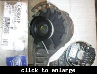
     Limiting Magneti Marelli 14V 60A Alternator Battery Charge Power to 150W with Flywheel
    Successfully tested it by connecting (B+ and B-) it to battery (B101/B102) and also (D+) to battery (B101/B102) via those 2 resistors (R101 and R102).
    When alternator speeds up D102 diode light nice goes low and alternator turns on...
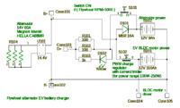
     Limiting Magneti Marelli 14V 60A Alternator Battery Charge Power to 150W with Flywheel

    But, i have no controll how much power or how big current will flow to connected battery from alternator while it has built in regulator.

    This what I'd like to do is what I've showed on schema above-limit output power to predefined level lets say 150W... because of i'd like to use flywheel powered by human and try to store energy in it and switch alternator only when its RPM is above eg. 1000 (to be determined for this model) while I will have power needed to charge big EV battery (B101).
    Small battery (B102) is only buffer there for powering alternator start and will be fully charged almost all the time, so I expect very small power needed to charge it, so voltage drop on diode D101 before this battery B102 is OK while it will work in buffer mode (acid or gel battery).
    The big one (B101) may be discharged much more (while used by EV BLDC motor), so more current needed and without any charge regulator (marked S102) maybe alternator regulator will try to get more power from alternator which simply will not be available, while it is no longer used in car, but in human powered EV bike, so RPM will quickly drop.
    That is why I'd like to make another switch (S101) controlled by small device which will switch it ON only when RPM is above alternator turn ON speed...
    Of course, I know how to limit current charge in this big battery (B101), but I'm NOT SURE, whether I can switch ON alternator (D+) via switch (S101) when alternator has speed lets say 2000 RPM and then switch S101 OFF when RPM drops to 999 RPM-without damage of build in regulator?

    So my idea was to use just 2 batteries like in this draw (small battery B102 secured by diode to be not discharged by low voltage on big baterry B101 during charging) and simply DO NOT disconnect ALL batteries from alternator (when it is turned on) using PWM for current regulation, but just only ONE-this big one B101 110Ah.

    Maybe, there is another solution howto bypass alternator built in regulator to limit its output power, based on its RPM?

    What do you think about it?
  • ADVERTISEMENT
  • #2 11289736
    Błażej
    VIP Meritorious for electroda.pl
    aneuron wrote:
    But, i have no controll how much power or how big current will flow to connected battery from alternator while it has built in regulator.

    Doesn't make any sense. Built in regulator is VOLTAGE regulator, which keeps voltage on right level. Current is result of load. It is not given, it depends on power consumption. If baterry will be empty, it takes maximum current. During charging current will decrease. You don't have to built in ane current regulators. Maximum current is limited by alternator construction (it is not going to give more, than it is in parameters).
    It is the same process like charging battery with simplest charger (transformer + rectifier, no elektronics). During charging current decreses and battery limits current itself.
  • ADVERTISEMENT
  • #3 11290599
    aneuron
    Level 12  
    Błażej wrote:
    Built in regulator is VOLTAGE regulator, which keeps voltage on right level. Current is result of load. It is not given, it depends on power consumption.

    So, it is OK. It works as expected-when I will use after alternator before big battery B101 PWM charge regulator (marked as S102), which will limit current at given battery voltage B101-this is common in any modern uP based battery charge regulator.
    Limiting average current in big battery B101(by swithing ON/OFF S102 using PWM) will result in less power needed, regadless how much B101 is discharged, so alternator should need less power from flywheel and it should result in less energy needed to keep flywheel running at speed above its "cut it" or turn on RPM... So I will try to keep alternator speed at defined RPM, and adjust power (current in B101 based on this min RPM and max power predefined in uP based regulators ) to keep this speed above "cut in",lets say 1000 RPM...
    What is wrong in this design?
    Changing PWM pulse we can change average current and limit it to given limits....
    I think it should work with good uP based PWM charge loader or other batery charger with current limiter (logicaly marked as switch S102)...

    My only issue was to design this circuit in the way I showed, that at any time at least one battery is connected to alternator, because of as I know alternator regulator would be sometimes destroyed if battery is disconnected while it is turned on at high RPM (tri diode reverse voltage limits)...

    UPDATE: This alternator battery (discharged to low 10.5V) charge test I hope will allow me to determine (from slow motion frame image analysis and known frame rate FPS) alternator turn on/off RPM and then we will see how it will perform with added uP current regulators and RPM controll circuits (connected in place of switch S102 and S101).


    Frame rate is 30 FPS so dt is: 1/30= 0.03333 s
    Bigger wheel diameter is: 0.160 m
    small one has: 0.060 m
    so 0.160/0.060= 2.67x
    Bigger wheel has 3 frames for full rotation when alternator turns ON, so:
    3x0.03333s=0.1s
    1/0.1= 10 Hz
    10 Hz*2.67= 26.7 Hz

    25 Hz= 1500 RPM
    26.7 Hz * 60obr/min= 1602 RPM
    30 Hz= 1800 RPM

    This means that alternator turn on was at 1500-1800 RPM.
    Maybe if battery voltage under this small load (~0.2A) was bigger than. 9.8V (its is discharged while has 10.4V without load) this turn on speed will change, but it is not a problem while I will have RPM controller...
  • ADVERTISEMENT
  • #4 11837435
    aneuron
    Level 12  
    My ideas goes to reality now and I've successfully bypassed oryginal Magnet Marelli alternator voltage regulator and reused for testing oryginal tri diodes.

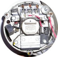
    Oryginal altegrator back looked like this:
     Limiting Magneti Marelli 14V 60A Alternator Battery Charge Power to 150W with Flywheel

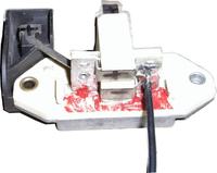
    Hacked voltage regulator to allow direct connection by 2 wires to have full controll of amount of current used as dynamic magnets.
     Limiting Magneti Marelli 14V 60A Alternator Battery Charge Power to 150W with Flywheel

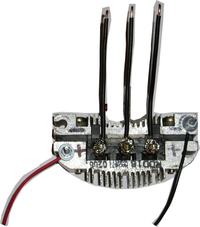
    Reused diodes for testing now are disconnected, but no problem to put them back again if needed.
     Limiting Magneti Marelli 14V 60A Alternator Battery Charge Power to 150W with Flywheel

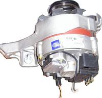
    After tuning now I have 3 phases wiring and 2 for D+ and D- (isolated from alternator case if needed). If oryginal tri diodes will be reused (and maybe 2.2uF oryginal capacitor) B+ and B- will be also available and no need for external 3phase bridge.

     Limiting Magneti Marelli 14V 60A Alternator Battery Charge Power to 150W with Flywheel

    This allows me now feed alternator with current of my choice and generate power at much lower RPM, than automobile version optimized for thousands RPM.

    NOTE: Youtube video will be downloaded soon, to show this is not only a concept.
    It is real and uP based ATTiny85 small driver will detect alternator RPM using SS495A magnetic field sensor and adjust ouput power to predefined limit. eg. 150W-250W to store human kinetic energy in FES for later use.
    I do not need 14V to speedup my FES, but needed to controll alternator power in its all RPM speed ranges.


  • ADVERTISEMENT
  • #5 11875651
    aneuron
    Level 12  
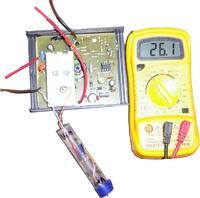
    Just testing mosfets VDSmax in acid battery charging mode using ATTiny85 running @ 8MHz & 125kHz prescaled ADC clock for voltage & current sensing using SS495A hall sensor.

     Limiting Magneti Marelli 14V 60A Alternator Battery Charge Power to 150W with Flywheel
    I'm using simple 1N4148 diode and capacitor 100V to catch and hold this Vmax voltage.

    IRFZ44Ns VDSmax here is 26.1V (beetween mosfet source and drain) and it is good, while its ratings are Min 55V.
    Now we are ready to modify this PCB and add sense for alternator RPM.
    I will simply remove potentiometer while it is not needed in automatic mode here and 2nd SS495A hall sensor will detect alternator RPM speed...

    BTW: So, no fired mosfets so far and new battery charge voltage & current regulator for bypassed alternator will be finished soon.
    Alternator output power will be under full controll at different RPM speeds as I wanted to do so...
  • #6 12108006
    aneuron
    Level 12  
    After a few more hours spend on this project, after longer brake, alternator primary coils switch is ready and i hope will sustain ON/OFF switching of this inductive load:
     Limiting Magneti Marelli 14V 60A Alternator Battery Charge Power to 150W with Flywheel
    Capacitor added for softer start and slower switch off.
    This driver is ready for power supply voltages higher than its IRF gate VGS spec-thanks to zener 12V diode on its gate limiting voltage to 10-12V.
    Tests showed that used IRFZ44N VSD voltage was only 0.005mV when load of 2x5W 12V light bulbs were switched ON/OFF using simply power supply from transformer with diodes at secondary voltage 18VAC. VGS voltage was 10V as expected, while 10V zenner diode inserted for testing.
    So,it is time now connect it to uC (PC817 optoisolator was used there) and integrate with its software to allow switch alternator ON/OFF based on its RPM required to generate voltage at given level and curent limited to predefined range, so power itself limited and adjusted using simple potentiometer on uP board....

    BTW: Of course when no signal from uC present, output mosfet in clossed state and no output power.
ADVERTISEMENT