logo elektroda
logo elektroda
X
logo elektroda

Car Alternator as High-Power 12-36V BLDC Motor - Affordable Driver Selection & Assembly

Mnster 26850 63
ADVERTISEMENT
Treść została przetłumaczona polish » english Zobacz oryginalną wersję tematu
  • #1 16706626
    Mnster
    Level 6  
    Hello!
    I need a high-power motor, powered by 12-36v, but I don't want to spend PLN 500 on the motor + controller.
    I came up with the idea to use a car alternator, read a bit about it and it turned out that I needed one
    modeling BLDC driver (I would build it myself but I do not have enough experience).
    I am asking for help in choosing a driver (as cheap as possible) and more information to put it together.
  • ADVERTISEMENT
  • #2 16706658
    Ture11
    Level 39  
    Gosh, it reminds me of the old days (hmm, 5 years ago) when I had ideas like that.
    Score:


    What I remember - the regulator was 80A (cheat, I have no way to write back to my colleagues from YT). I don't think it is suitable for long-term work. There were terrible problems with setting the excitation current - it came from a laboratory DC power supply (CC) and giving too little current caused the driver to get lost in rotating the motor, too high current also caused a significant slowdown of the motor (you can hear it in the YT movie, like a motor "hums" and walks heavily - the current was too high).

    It can be done ... But setting the "set point" will be a pain. Anyway, alternators were not made for such work and it will be hard to talk about efficiency - it is probably better to hunt an engine than a wheelchair scooter.

    It can, but it
  • #3 16710185
    Mnster
    Level 6  
    Thanks for the answer! I have read a bit about it and in fact such a solution is quite problematic.

    Added after 7 [minutes]:

    Generally, I need such a go-kart engine (possibly a bit higher than a typical go-kart). I can't find any such powerful engine as cheap. Where can you get such an engine from? Is a 350-watt engine enough to power such a vehicle? I have the option to buy the 350 W motor only for PLN 94.
  • #4 17129255
    Mnster
    Level 6  
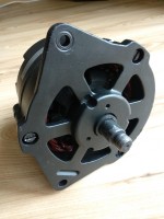
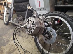
    Hello! Recently I was able to run the alternator as an engine and it works surprisingly well. The alternator only needs a minor modification (you need to remove the rectifier and lead the cables from the phases to the outside) I power it with a Chinese 48v 350w e bike driver, additionally 12v given to the rotor brushes.
    I include a link to buy the driver if someone is interested:
    https://en.aliexpress.com/item/OOTDTY-Alumini...rushless-DC-Motor-Controller/32841355316.html
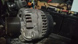
    In the attachment there is a photo of the converted alternator (I cleaned and painted it to make it look nice :D ).
  • ADVERTISEMENT
  • #5 17788837
    jestemgrafikiem
    Level 1  
    Mnster wrote:
    Hello! Recently I was able to run the alternator as an engine and it works surprisingly well. The alternator only needs a minor modification (you need to remove the rectifier and lead the cables from the phases to the outside) I power it with a Chinese 48v 350w e bike driver, additionally 12v given to the rotor brushes.


    Hi,

    Forgive me for the excavation, but I am interested specifically in how you connected the controller to the alternator?
    Did you use exactly the same wires as in the controller (blue, yellow, green)?

    What about the other cables (except for the controller power supply)?

    Greetings
  • #6 17789345
    Mnster
    Level 6  
    jestemgrafikiem wrote:
    Mnster wrote:
    Hello! Recently I was able to run the alternator as an engine and it works surprisingly well. The alternator only needs a minor modification (you need to remove the rectifier and lead the cables from the phases to the outside) I power it with a Chinese 48v 350w e bike driver, additionally 12v given to the rotor brushes.


    Hi,

    Forgive me for the excavation, but I am interested specifically in how you connected the controller to the alternator?
    Did you use exactly the same wires as in the controller (blue, yellow, green)?

    What about the other cables (except for the controller power supply)?

    Greetings


    After removing the rectifier module from the alternator, I connected the 3 outgoing winding wires with the wires from the controller (blue, green, yellow). In addition, you need to connect the appropriate speed control handle to the controller. You should also pay attention to whether the controller can work in sensorless mode (without hall sensors), in my description it says that it does not work without sensors, but in practice there is no problem with it. with "+" power to turn on the controller.
  • #7 17893427
    rdt
    Level 25  
    Hello
    And have you thought about sticking those unfortunate Halli? how did you translate? I once connected to the controller (only one without a housing) and it was spinning nicely, but I had a series of 120Ohm / 20W (2x240Ohm / 10W) in the rotor circuit (I will say that under one of the transistors, the tin was literally boiling (boiling), how badly the rotor current was selected .
  • #8 17893808
    Mnster
    Level 6  
    rdt wrote:
    Hello
    And have you thought about sticking those unfortunate Halli? how did you translate? I once connected to the controller (only one without a housing) and it was spinning nicely, but I had a series of 120Ohm / 20W (2x240Ohm / 10W) in the rotor circuit (I will say that under one of the transistors, the tin was literally boiling (boiling), how badly the rotor current was selected .


    It seemed to me that the installation of these sensors would be complicated, so I did not even try it. If the RPM increases slowly, the engine start is not a problem. Perhaps your controller had too weak transistors, even without regulating the rotor current (12v battery) nothing in the controller it does not heat up, what specific gear ratio do you mean?
  • ADVERTISEMENT
  • #9 17894874
    rdt
    Level 25  
    Hello
    I mean the gear. - did you use a mechanical transmission, I ask because my observations show that the engine has its optimum in a certain range of revolutions.
    When I tried to start the engine, it had very little power at very little revs.
    Show photos of the go-kart because I'm curious about the construction.
  • #10 17895157
    Mnster
    Level 6  
    Ah, now I remember :)
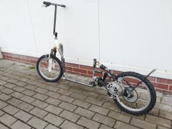
    Unfortunately, the go-kart project didn't work out, but I'm currently trying to build an electric scooter powered by an alternator.
    Plans to do 3: 1 gear on gears and 5mm HTD belt.
    If I manage to do something, I will approve.
  • #11 17909556
    LemuRR 11
    Level 26  
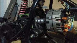
     Car Alternator as High-Power 12-36V BLDC Motor - Affordable Driver Selection & Assembly  Car Alternator as High-Power 12-36V BLDC Motor - Affordable Driver Selection & Assembly  Car Alternator as High-Power 12-36V BLDC Motor - Affordable Driver Selection & Assembly

    I can see that I am not the only one. I stick to the topic, the construction will not be finished ;)

    Edit:
    I will add that there is no such thing as a "working point"
    By changing the excitation current, the torque changes. The power remains the same.
    So it would be a shame not to take advantage of this advantage.
    For me, step control 7V 5V 3V.
    I will add that the modification of the good alternator from poldek did not end with the dismantling of the diodes.
    At the factory, the winding is star-connected, which limits the power of our motor quite significantly.
    For me, it was possible to desolder the place where the windings were connected.
    In a triangle configuration, the results are much better for my eyes.
  • #12 17925079
    rdt
    Level 25  
    Hello
    How do you regulate these 7V 5V and 3V? What driver do you have to regulate the voltages on the stator?
    To be honest, in my case, dry, without load, the engine rotated better with less voltage on the rotor.
  • #13 17926274
    LemuRR 11
    Level 26  
    Converter on LM2596, and the regulation is done by 2 relays that change the resistors in the feedback.

    It was spinning better because you had less braking torque. However, the lower the rotor current, the lower the torque, and thus the higher the maximum speed. More momentum when starting and going uphill is very useful.

    The driver is a model ESC 100A, with an additional heat sink. When loaded with the second alternator, he calmly gave advice, not warming up anyhow.
  • #14 17926934
    rdt
    Level 25  
    Have you measured the rotor current at 3V 5V and 7V?
  • #15 17927078
    LemuRR 11
    Level 26  
    rdt wrote:
    Have you measured the rotor current at 3V 5V and 7V?


    The winding resistance is 3.5 ?
    For 7V it comes out 2A.
  • #16 17928212
    rdt
    Level 25  
    Give me some driving videos
    ps I turned my alternator with such a driver.
    Link to the auction
    Of course, I added a heat sink and a smice.
    If you can ask, I'd like to see the rack mount to the alternator axle.

    one more thing - should the alternator as an engine not be "forced to rotate the other way? because:
    If it is driven by the engine and it is it that resists, if it turns slower because of the slip, let's call it negative because the altar turns slower than the system, so the nut must be set so that it tightens at the same time.
    On the other hand, with a positive slip, i.e. when the gazebo turns faster than the system, the opposite phenomenon will occur.
    I just looked at my alternator and I can see that the arrow on the housing (direction of rotation) is in the other direction than the logic ordered.
    I quickly compared it with an angle grinder because it tightens at 999% there - and the direction is different, both threads are normal right
  • #17 18311354
    Witch44
    Level 10  
    Hello.
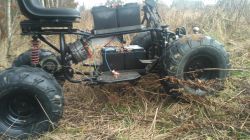
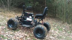
    By connecting to the topic, I was able to try the alternator as an engine to drive the quad bike. Surprisingly, it turned out great.
    -Quad ATV 150
    -Alternator Valeo 150A (only the regulator cut off, without interfering with the connection of the stator windings, Hall sensors - there was no need, very smooth operation)
    -Chinese driver 48-72v 1500W (momentary 2200W)
    -Common 44 Ah car batteries
    - Excitation of the rotor, optional 1-2A (bulbs from the car are ideal, in both cases there is no problem with starting even under load)
    - 1:40 gear
     Car Alternator as High-Power 12-36V BLDC Motor - Affordable Driver Selection & Assembly
  • #18 18312766
    Witch44
    Level 10  
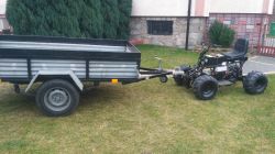
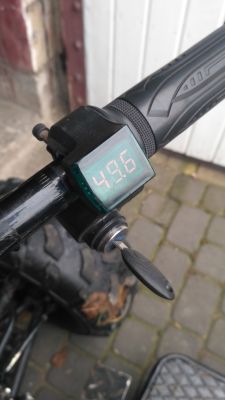
     Car Alternator as High-Power 12-36V BLDC Motor - Affordable Driver Selection & Assembly  Car Alternator as High-Power 12-36V BLDC Motor - Affordable Driver Selection & Assembly  Car Alternator as High-Power 12-36V BLDC Motor - Affordable Driver Selection & Assembly  Car Alternator as High-Power 12-36V BLDC Motor - Affordable Driver Selection & Assembly
    After 51V charging. After 40 minutes of playing in the field and pulling a 49V trailer.
    Warm engine, not hot. Time to put it together nicely.
  • #19 18313097
    398216 Usunięty
    Level 43  
    Witch44 wrote:
    After 40 minutes of playing in the field and pulling the trailer
    Judging by the setting of the seat - pushing ...
  • #20 18313300
    Witch44
    Level 10  
    the vehicle moves in both directions :wink:
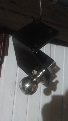
    the rear hitch is still drying  Car Alternator as High-Power 12-36V BLDC Motor - Affordable Driver Selection & Assembly
  • #21 18313680
    rdt
    Level 25  
    as I wrote about the direction of rotation and sliding, I meant mechanical slip - resulting from weight and inertia. Is your nut somehow secured against unscrewing?
  • #22 18314435
    LemuRR 11
    Level 26  
    How about the idle current in your case? For me, unfortunately, the alternator from FSO turned out to be a weak link. Pretty warm. And the no-load current is much too high (10A)
  • #23 18315626
    Witch44
    Level 10  
    rdt- I gave up the wheel tightened with a screw. I sanded the spline on the rotor axis. I touched the axis overlapping the rotor axis with the defects in the form of the nut thread and filled with metal filler. I tightened the whole thing from the forehead with a screw.
    Effect - trying to shorten the axis, there was no chance of breaking both elements in half. On the newly created axle, another groove, this time for a steel wedge and an aluminum clutch.

    LemuRR 11- no-load current 2A + 2A excitation. Browsing through dozens of posts on various pages, I have noticed a frequently discussed topic of iron supersaturation used to build the Stojan, there is something to it. At the moment my driver is set to 70% power. earlier, at 100-120%, actually at 3-4 amps of excitation, the motor was able to suddenly "jump into the resistance", drastically increasing the power consumption and reducing the revolutions. The temperature then rises quickly. Only reducing the excitation current helped.
    One thing is interesting, namely the gear ratio. It can be crucial. if it is too small, the alternator is very electricity-consuming, like any other engine that will be heavily loaded. My 1:40 may be too exaggerated. Altek makes a sound like a nice speeding turbine, but even leaning against the wall, grinding the wheels I cannot exceed 30 amps (the system has a 30A ammeter). Off-road driving (photos above), maximum consumption about 12A. The driver can give 50A, which it will never achieve because my current protection ends at 32A. The alternator from the Iveco 28V 90A truck will soon be tested. I wonder if there will be any difference :wink:
  • #24 18324834
    Witch44
    Level 10  
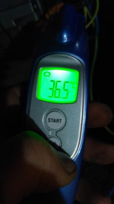
    Further tests. One and a half hours this time. The engine felt hot to me, but it turned out otherwise.  Car Alternator as High-Power 12-36V BLDC Motor - Affordable Driver Selection & Assembly
    By the way, the question, namely the problem with excitation. At the moment, the rotor is still powered from 12V in series with the H4 bulb, current 2A.
    Ultimately, I would like to supply the rotor with 48V and somehow I can't find a solution here. While the bulb connected in series at 12V works well, at 48V 4 bulbs connected in series give too much current. This is still 2A, and I think it should be 0.5A at this voltage to do the same job. I tried voltage-reducing converters, but these simply in the world either get stupid or die after a while. I tried to filter the current at the output before the rotor, but to no avail. Any ideas?  Car Alternator as High-Power 12-36V BLDC Motor - Affordable Driver Selection & Assembly  Car Alternator as High-Power 12-36V BLDC Motor - Affordable Driver Selection & Assembly
  • #25 18328328
    rdt
    Level 25  
    a separate jelly for excitation? such an alarm, say 7 or 9 Ah?
    Do you have photos of this altka shaft as you carved it?
  • ADVERTISEMENT
  • #26 18329503
    jarek_lnx
    Level 43  
    Witch44 wrote:
    I tried voltage-reducing converters, but these simply in the world either get stupid or die after a while. I tried to filter the current at the output before the rotor, but to no avail. Any ideas?
    There are two possibilities, or power surges caused by impulse current consumption by the motor controller, which can be reduced by using an LC filter and a TVS diode, it is also worth using separate wires from the battery. As a last resort, a separate battery.

    The inductive load itself should not interfere with the inverter output if it is constantly energized, but it is possible that this winding is induced by pulses by impulse supply of the stator, and here the LC filter should help. LC filters are used when the RC filter would cause too much loss, what is the excitation current?
  • #27 18330626
    Witch44
    Level 10  
    Excitation current without bulb at 12v is 2.7A.
    With a 2A bulb, i is optimal. The rotor feed system is fed separately. The converters worked fine until I powered the stator, so there may be something to it.

    Added after 18 [minutes]:

    When it comes to filters, I used both the Upper and the Lower pass. Unfortunately, in the dark, without an oscilloscope, it is reading tea leaves.
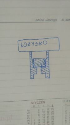
    Rdt- I did not take pictures of the axles, when I come back from work I will try to make an overview drawing
  • #28 18331377
    jarek_lnx
    Level 43  
    Witch44 wrote:
    When it comes to filters, I used both the Upper and the Lower pass. Unfortunately, in the dark, without an oscilloscope, it is reading tea leaves.
    I would rely on a large electrolytic capacitor parallel to the excitation winding and the inverter input, say 4700uF, and separate it from the source with a 100uH-1mH choke
  • #29 18333092
    Witch44
    Level 10  
    rdt- I hope the drawing is quite legible. Lots of work before Christmas and no time at all. It remains to pick after the night :crazyeyes:  Car Alternator as High-Power 12-36V BLDC Motor - Affordable Driver Selection & Assembly
    Axis section.
  • #30 18357119
    Witch44
    Level 10  
    An alternator from IVECO came. Time for a comparison :D  Car Alternator as High-Power 12-36V BLDC Motor - Affordable Driver Selection & Assembly

Topic summary

The discussion revolves around the feasibility of using a car alternator as a high-power BLDC motor powered by 12-36V, focusing on affordable driver selection and assembly. Users share experiences and challenges related to modifying alternators for motor use, including the removal of rectifiers and connecting to various controllers. Key points include the importance of excitation current management, the effectiveness of different wiring configurations (star vs. delta), and the use of specific controllers like the Chinese 48V 350W e-bike driver. Users also discuss the performance of different alternators, such as those from Valeo and IVECO, and the potential of washing machine motors as alternatives. The conversation highlights the need for careful tuning of rotor currents and the impact of gear ratios on performance.
Summary generated by the language model.
ADVERTISEMENT