logo elektroda
logo elektroda
X
logo elektroda

T-CON LOGIKA 260AP01C2LV1.3 - Image Issues, Damaged Diode Replacement, Voltage Analysis

PF 18057 16
ADVERTISEMENT
Treść została przetłumaczona polish » english Zobacz oryginalną wersję tematu
  • #1 12395916
    PF
    Level 19  
    Hello !
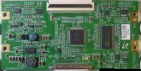
    The problem is what you can see in the photo:

    T-CON LOGIKA 260AP01C2LV1.3 - Image Issues, Damaged Diode Replacement, Voltage Analysis

    At the top of the picture as if not all lines are displayed, and a white glow sometimes appears on the screen.

    Before these symptoms, the television was completely dead.
    The D11 diode on the T-CON [shown in the photo] was damaged, the T-CON fuse is OK.
    After replacement, the TV set started with such symptoms. Besides, at the moment the UC8 circuit heats up much more than the others [you can say that it burns].
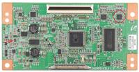
    T-CON LOGIKA 260AP01C2LV1.3 - Image Issues, Damaged Diode Replacement, Voltage Analysis

    The voltages at the moment on T-CON are:

    Vin 12V
    VDD = + 3.2V
    VR = + 8.4V
    VON = + 25.6V
    VOFFE = - 9.9V
    VSS = - 7.5V
    CVO = + 8.3V
    AVDD = + 13.9V

    Does this symptom result from a damaged T-CON, or are there any other measurement points that will help better in diagnosis?

    The matrix that occurs there is:

    T-CON LOGIKA 260AP01C2LV1.3 - Image Issues, Damaged Diode Replacement, Voltage Analysis

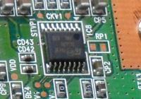
    ps. Can someone help decode what's scribbled on UC8:
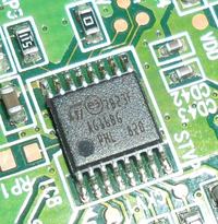
    T-CON LOGIKA 260AP01C2LV1.3 - Image Issues, Damaged Diode Replacement, Voltage Analysis
  • ADVERTISEMENT
  • #2 12396267
    lisek
    Service technician RTV
    As for the "scribbles" on UC8, match one of the ICs on this pcb board for the identical matrix 32 "LTA320AP02

    Quote:
    LVDS LMX6322T1 controller
    DC-DC _TPS65160A
    Other IC on board: i7822, MAXIM 5678E, ST AG32AE2, EM638325TS-7G, 043Z, P2042AF, 416WP, KXBZ W866FB;
    OP1, OP2 - i7814HS (17814HS) buffers

    VIN - 12V
    * fed to the matrix through ??3401

    AVD0, AVDD_1 - 14.6V
    VON - 27.6V
    VOFF - * with negative (-10.7) V
    VSS - * with a negative (-7.5) V
    VR, CVO - 9V
    VDD, VCC - 3.3V
    VREFU_H - 14.5V
    VREFU_L - 8.5V
    VREFL_H - 6V
    VREFL_L - 0.1V


    As for Maxim and their descriptions on the housing, useful Link
    e.g. description of BKX ... we get MAX9650
    BKP description - MAX15032AT
    ______________
    You have a problem in one / several CKV2, CKVB2 signals
    * (CKV1, CKVB1, CKV2, CKVB2, STVP2, STVP1)

    Read about MAX17121? (AG32AE2) and how are these signals given?
    http://datasheets.maximintegrated.com/en/ds/MAX17121.pdf
    How can Voff be adjusted
    http://www.fotolink.su/v.php?id=3a91f0ffa73b343af9243dd85225557e

    If you do not have a problem in the matrix (replacement) !?
    ________________

    Diode after the code z Link_download e.g. from this page
    Field_link SI7820DN

    This is the one from 32 "
    T-CON LOGIKA 260AP01C2LV1.3 - Image Issues, Damaged Diode Replacement, Voltage Analysis
  • ADVERTISEMENT
  • #3 12396554
    PF
    Level 19  
    The tensions you gave me:

    AVDD, AVDD_1 - 13.9V
    VON - 25.6V
    VOFF - - 9.9V
    VSS - -7.5V
    VR, CVO - 8.4V
    VDD, VCC - 3.2V
    VREFU_H - 13.7V
    VREFU_L - 8.1V
    VREFL_H - 5.7V
    VREFL_L - 0.2V

    I replaced the damaged diode with MMBD7000LT1G
    http://www.tme.eu/pl/details/mmbd7000lt1g/diody-uniwersalne-smd/on-semiconductor/#

    You write that I have a problem in CKV signals.
    This "scribbled" circuit is the one that heats up so terribly.
    It's probably AG168G [http://xccfl.com/product_info.php?products_id=548].
    As it can be seen from the description on T-CON, he is responsible for CKV1.

    T-CON LOGIKA 260AP01C2LV1.3 - Image Issues, Damaged Diode Replacement, Voltage Analysis

    Is it possible to check it to clearly determine the damage to the system or matrix?

    And by the way, is it possible to buy this miracle somewhere or replace it with anything else.
    Uncle GOOGLE is not very talkative about him.
  • #4 12397956
    lisek
    Service technician RTV
    O T-con T-CON - 320AB02CP2L (zobacz na foto., jak wygląda) napisano swego czasu

    Quote:
    The board T-con there are two drivers in positions ICS1 and ICS2 from which signals STVP1, CKVB1, CKV1 and STVP2, CKVB2, CKV2 go to the row driver ... on matrix ,
    * zobacz jakie to IC owe ICS1/ICS2

    1 group and group 2 drivers (as it is there precisely arranged known only to developers but let's say that one group of duplicates another group) so that's one of the groups has a broken drivers register which spoils us a picture, in my case it group1 controlled by signals from the respective index 1 through driver ICS1. 
    Evaluate to what group broken off the register in turn supply with Von ICS1 And ICS2, and landing legs 1 chip on the body where the shots will no longer run after disconnecting Von, then that driver controls the group with broken case. It may seem that removing power from Von (28v) with a driver problem is solved, but this is not true, but the picture becomes different but over time 5 minutes if the image is static objects such as a channel logo , then there artifacts in the form of intermittent strips cm photos. 
    But this is also solved simply be removed from the board and apply for a driver signals STVP, CKVB, CKV power Voff (-12v) 8 foot chip driver. And in general, is all the picture is almost perfect! , Only fifteen minutes on the logo channel was seen barely noticeable artifact, little discernible if you do not know where to look not uvidesh, it is possible to win by increasing negative voltage Voff to-16 --- 17volt. 
    When installed Voff 16.3V, regulation Voff with realized Zener diode 9,1 v included as shown in the picture (between the emitter and the collector of Q2, to the emitter cathode, the anode to the collector)....


    Można spróbowac odłaczyć od buffera sygnały CKVB i/lub CKV.
    Można podać zwiększone nap. Voff (np.16V) na pkt. STVP,CKVB,CKV
    *wszystkie lub wybrane , metoda eksperymentów

    Uszkodzenie masz w samym scalaku ? (grzanie sie ) lub w połączenaich sciezek
    matrycy idących do (Gate Driver)


    Nie ma gotowca , metoda prób i błędów
    ____________
    T-CON LOGIKA 260AP01C2LV1.3 - Image Issues, Damaged Diode Replacement, Voltage Analysis
    Quote:
    CKV to NIE stałe napięcie , a IMPULSY o amplitudzie (rozmachu) od VGL (V_OFF) do VGH (V_ON).

    ** jak masz te sygnały WIESZ wszystko o VON i VOFF

    ** STV jest tak ważny , trzeba miec dobry oscyloskop ,zeby go zobaczyć!
    ** czasem nap. VR (koło i7814HS), 8.74V

    Voff można regulować np. z (-12V) do (-15-17V).. ale trzeba znać jak realizowana jest ukł. przetwornica DC-DC robiąca nap. Voff

    Ten IC AG168G tylko w Chinach i trzeba brać min. 10szt. (wtedy cena ok. 5$/szt) +wysyłak
  • ADVERTISEMENT
  • #6 12398086
    lisek
    Service technician RTV
    Ja myślę, że od sprawdzenia "standartowo" owe +3,3v autor rozpoczał pomiary.

    __________
    Tak dla dociekliwych
    Quote:
    At startup Voff was around -18V then quickly drop to -10V
    As result ICS2 become very hot,thinking that's the problem,search and find another one but after replacing problem still present.
    Searching I found your solution,then I make wire connection from Voff to STVP1,CKVB1 and CKV1 like in picture.
    Can't find 9.1V zenner diode so I made one from two 5V ones (in fact result is around 9.7V) and Voff is around -16.7V.

    Now ICS2 run just a little warm.
    But a little problem still exist,after show up menu in 1-2 seconds appear some vertical lines as trails from OSD.

    za Link_filmikiem
  • #7 12427517
    PF
    Level 19  
    Fox can you direct me on the topic from which the quote above comes.
  • #8 12430933
    PF
    Level 19  
    There is 3.3V at the output of the power supply 3.5V . Could that be about this problem.
  • #9 12431175
    lisek
    Service technician RTV
    Quote:
    There is 3.5V at the output of the power supply 3.3V. Could that be about this problem.


    Maybe!?

    On what IC is these 3.3V made?
    What's your nap. input?
  • #10 12574169
    PF
    Level 19  
    I was a bit absent, but it was a force majeure.
    In the meantime, for a moment I got an identical T-con for replacement and the effect was the same [identical image and heating scalak].

    3.3 V I have made on MIP2H2.
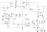
    T-CON LOGIKA 260AP01C2LV1.3 - Image Issues, Damaged Diode Replacement, Voltage Analysis

    Is it possible that I have a voltage of about 0.2V on legs 1 - 4 8-O [all four legs].
  • ADVERTISEMENT
  • #11 12574696
    bogred
    VIP Meritorious for electroda.pl
    PF wrote:
    Is it possible that I have a voltage of about 0.2V on legs 1 - 4 8-O [all four legs].


    Why would it be impossible? If the meter is operational, you measure correctly and this result comes out ... Another thing is whether these voltages are correct :D The answer to this question is rather negative :cry:
  • #12 12574809
    PF
    Level 19  
    The meter seems ok.
    Maybe different: can these voltages be measured with an ordinary multimeter?

    Does their absence indicate damage to MIP2H2 [could the symptom shown above be the result, whether the TV would work if it was damaged]?

    ps. A little bit of these: are ...
  • #13 12574967
    bogred
    VIP Meritorious for electroda.pl
    I'll give you a hint of a good way: there is something like Google. I type MIP2H2 and here's what I see: (for example) http://www.google.pl/imgres?imgurl=http://obr...g&imgrefurl=https://www.elektroda.pl/rtvforum/ topic1764104.html&h=581&w=860&sz=81&tbnid=W4RpjLyXSd_GQM:&tbnh=82&tbnw=121&prev=/search%3Fq%3Dmip2h2%26tbm%3Disch%26tbo%3Du&zoom=1&q=mip2h2&usg=__95xCqeIz7sIqGxSZqo5TFRl1_FE=&docid=HZKswlMPG1D4DM&sa=X&ei=tsr2UdWhFYPfOJHggcgI&sqi=2&ved=0CCwQ9QEwAA&dur = 860
    Even the tensions are given ...
  • #14 12575000
    PF
    Level 19  
    I saw this diagram and expected similar tensions. Only in my case there is approx. 0.2V on legs 1-4.
  • #15 12575337
    mirex
    Level 43  
    mirex wrote:
    Auxiliary question - what do the regulations say about the title of the topic (point 3.1.15) and its extension: https://www.elektroda.pl/rtvforum/topic1796351.html point 3?
    Will you please?

    Yeah ... great thing with this inverter!
    Explain where you got the 3V from then. Ooo! - sorry, 3.5V for the transformer that this MIP controls.
    PF wrote:
    Maybe different: can these voltages be measured with an ordinary multimeter?

    Nice too.

    I have a question - why have you decided to measure these tensions?

    Come on, look fox. You've worked so hard, and here you are! ;)
  • #16 12577109
    lisek
    Service technician RTV
    T-CON LOGIKA 260AP01C2LV1.3 - Image Issues, Damaged Diode Replacement, Voltage Analysis Col. mirex ..... have you seen this "color diagram" on Link_ I'm too late

    Maybe this is the answer to your "surprise".
  • #17 12577454
    PF
    Level 19  
    The only thing on this forum is making fun of others. Only geniuses and the rest of the morons. Why create a section for beginners, if no one will tell you anything matter-of-fact only in every sentence proves your superiority over others. Oh, I am stupid, I thought that something in our world was changing, but the SERVICEANTS care so much about their money that they will not help anyone, so that sometimes nobody learns too much. As a Pole is to a Pole - the whole world knows this rule.

Topic summary

The discussion revolves around image issues in a television related to the T-CON board model LOGIKA 260AP01C2LV1.3. The user reports symptoms such as incomplete line display and a white glow on the screen after replacing a damaged D11 diode. Voltage readings on the T-CON board are provided, indicating potential problems with CKV signals and overheating of the UC8 circuit. Various suggestions are made, including checking the voltages at different points, experimenting with signal disconnections, and considering the possibility of matrix damage. The user also inquires about the MIP2H2 IC and its voltage outputs, which are found to be significantly lower than expected. The conversation highlights troubleshooting steps and the need for further diagnosis to identify the root cause of the issues.
Summary generated by the language model.
ADVERTISEMENT