Hi,
i'm making a second attempt to control a (supposedly smart) house.
First a description of the electrical solution.
I have a couple of crossover boxes in the attic which contain:
- relays controlled from the main cabinet,
- inputs from all the switches are collected, sent to the main cabinet.
Everything goes on wires.
A total of about 64 inputs and 64 outputs - I plan to possibly expand with other peripherals.
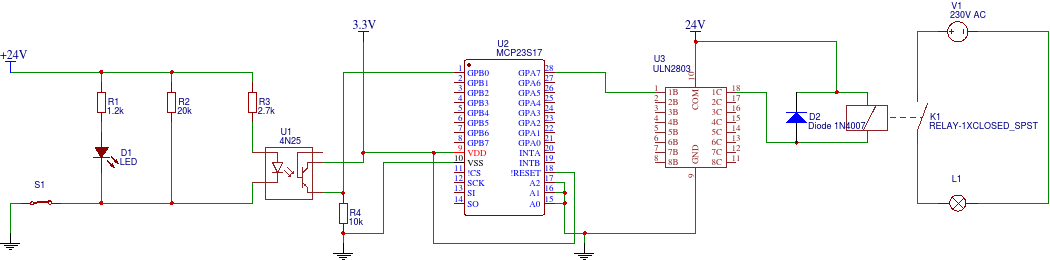
The first approach was based on an arduino, a couple of 74HC595, 4021, 4N25 ground and finder relays (24V coil). The control system was in the main cabinet. I have two power supplies in the cabinet - 5 and 24 volts.
I picked up my knowledge of these circuits from the arduino helps somewhere.
Problems I encountered:
- optocouplers couldn't control relay coils - at first I had a lot of relays with more sensitive coils, then the situation changed.
- interference from relays (total lack of knowledge of how to deal with this), then I just got the idea to use at least rectifier diodes;
- long start-up time - I struggled for a long time with the software in the arduino. I went too much into trying to hook up the software to the internet at the beginning, instead of focusing more on handling the ICs.
After which the project wasn't finished and at one point I gave up on the control and wired everything up in the main cabinet and it works too.
Since I have a raspberry lying around in my drawer - I want to start the fun all over again:
- first of all I need help in preparing the right circuits - and for this I need knowledge and your help.
One thing I won't change - the relays with 24V coil and the wiring already laid.
1. How do I design/select the circuit so that I can control the relays stably and without major disturbances? (Relay: electromagnetic; SPDT; Coils :24VDC; 16A/250VAC, FINDER 40.61.7.024 or similar) - of course I want to galvanically isolate the control system from the relays.
2. What ICs should I use to stage the outputs and collect the inputs? As my soldering skills are not top class I prefer DIP enclosures. I2C preferred.
3. Software. Does anyone have experience with any open source projects? I am most comfortable with a python/php combination.
i'm making a second attempt to control a (supposedly smart) house.
First a description of the electrical solution.
I have a couple of crossover boxes in the attic which contain:
- relays controlled from the main cabinet,
- inputs from all the switches are collected, sent to the main cabinet.
Everything goes on wires.
A total of about 64 inputs and 64 outputs - I plan to possibly expand with other peripherals.
The first approach was based on an arduino, a couple of 74HC595, 4021, 4N25 ground and finder relays (24V coil). The control system was in the main cabinet. I have two power supplies in the cabinet - 5 and 24 volts.
I picked up my knowledge of these circuits from the arduino helps somewhere.
Problems I encountered:
- optocouplers couldn't control relay coils - at first I had a lot of relays with more sensitive coils, then the situation changed.
- interference from relays (total lack of knowledge of how to deal with this), then I just got the idea to use at least rectifier diodes;
- long start-up time - I struggled for a long time with the software in the arduino. I went too much into trying to hook up the software to the internet at the beginning, instead of focusing more on handling the ICs.
After which the project wasn't finished and at one point I gave up on the control and wired everything up in the main cabinet and it works too.
Since I have a raspberry lying around in my drawer - I want to start the fun all over again:
- first of all I need help in preparing the right circuits - and for this I need knowledge and your help.
One thing I won't change - the relays with 24V coil and the wiring already laid.
1. How do I design/select the circuit so that I can control the relays stably and without major disturbances? (Relay: electromagnetic; SPDT; Coils :24VDC; 16A/250VAC, FINDER 40.61.7.024 or similar) - of course I want to galvanically isolate the control system from the relays.
2. What ICs should I use to stage the outputs and collect the inputs? As my soldering skills are not top class I prefer DIP enclosures. I2C preferred.
3. Software. Does anyone have experience with any open source projects? I am most comfortable with a python/php combination.