logo elektroda
logo elektroda
X
logo elektroda

The DTSU666 bidirectional, three-phase electricity meter and data retrieval via Modbus on the ESP32

p.kaczmarek2 1497 12

TL;DR LABEL_AI_GENERATED

  • A DTSU666 DIN-rail, bidirectional three-phase energy meter is integrated with an ESP32 to expose live electrical data beyond a closed vendor ecosystem.
  • An ESP32 LilyGO T-CAN485 polls the meter over RS485/Modbus RTU, combining two 16-bit registers into scaled 32-bit floating-point measurements.
  • The DTSU666 costs about 250 zł, occupies four DIN modules (72 mm), and supports Modbus slave addresses from 1 to 247.
  • The setup reads per-phase voltage and current, active/reactive power, power factor, frequency, and imported/exported energy for web displays, databases, or Home Assistant.
  • RS485 requires an appropriate transceiver rather than direct UART wiring, and long bus runs should use 120 Ω termination resistors at both ends.
AI summary based on the discussion. May contain errors.
ADVERTISEMENT
This content has been translated flag-pl » flag-en View the original version here
Listen:
  • The DTSU666 bidirectional, three-phase electricity meter and data retrieval via Modbus on the ESP32
    The DTSU666 is an electronic, three-phase energy meter designed for mounting on a DIN rail within a switchboard. Thanks to its built-in RS485 interface and support for the Modbus RTU protocol, this meter is well suited to reading real-time data on voltages, currents and power, allowing for easy integration into your own projects. This is exactly what I’ll be demonstrating here, using a ready-made ESP32 board.
    The DTSU666 bidirectional, three-phase electricity meter and data retrieval via Modbus on the ESP32
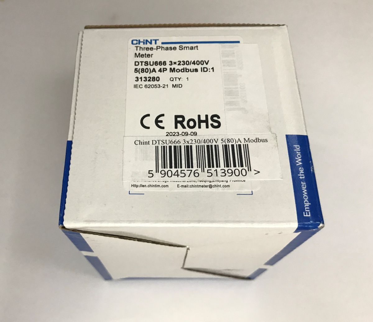
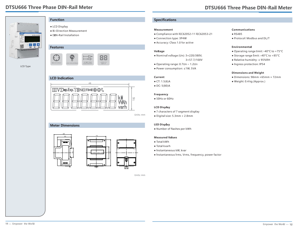
    I bought the DTSU666 from a Polish online shop for around 250 zł. The device occupies 4 standard DIN modules (72 mm wide) in a switchboard and weighs just under 400 grams. It is also fitted with a backlit LCD display, which allows you to conveniently view the current voltage, currents and energy metered on individual phases without the need for any additional apps, as well as to configure Modbus. The pack also included a Polish-language manual.
    The DTSU666 bidirectional, three-phase electricity meter and data retrieval via Modbus on the ESP32 The DTSU666 bidirectional, three-phase electricity meter and data retrieval via Modbus on the ESP32 The DTSU666 bidirectional, three-phase electricity meter and data retrieval via Modbus on the ESP32
    Connecting the DTSU666 is fairly straightforward – even the sticker on the side lists the pins, including the RS485 port and the pulse output.

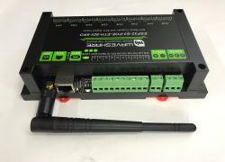
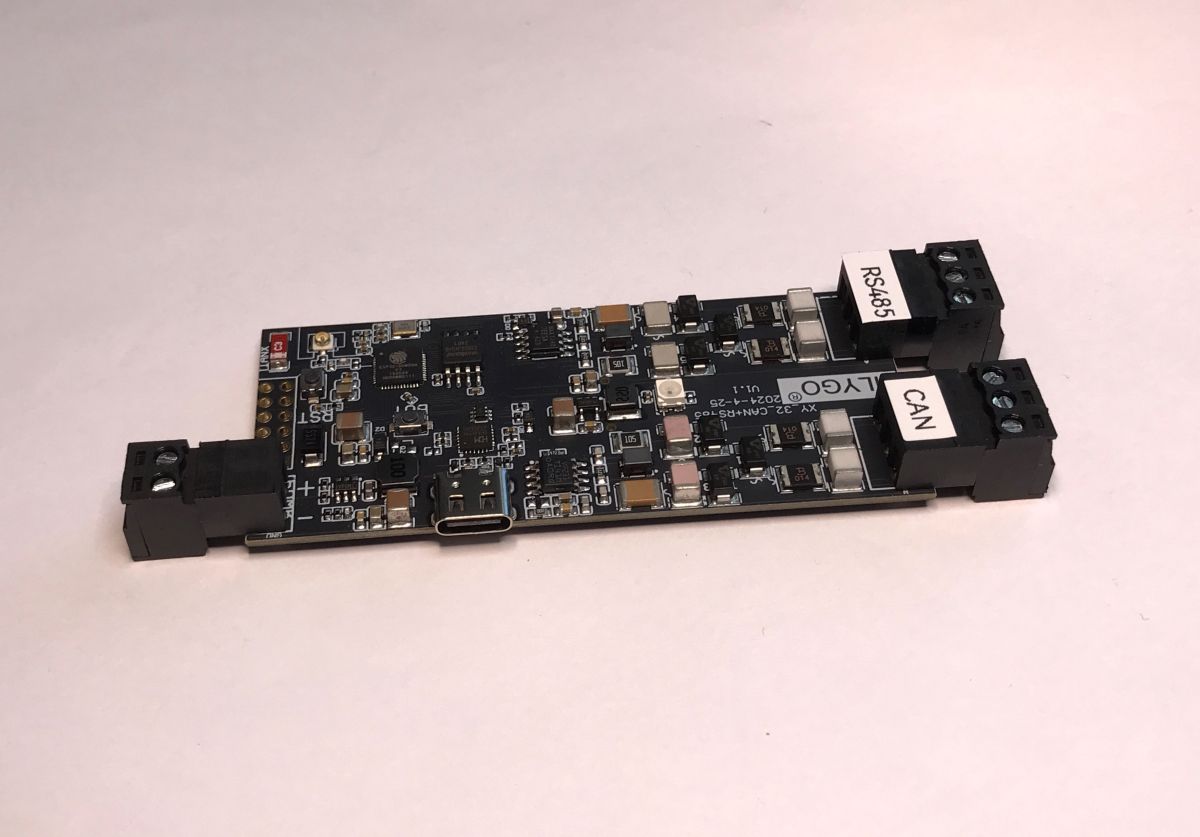
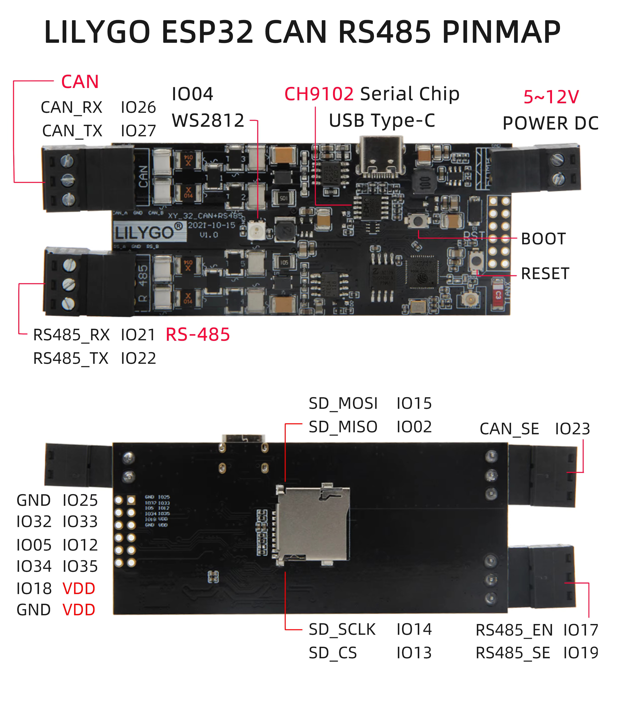
    The RS485 port is used here for communication via the Modbus RTU protocol, which is widely used in industry. RS485 itself is merely a physical layer based on a differential signal, providing high resistance to interference and ranges of hundreds of metres. From the microcontroller’s perspective, it is handled in exactly the same way as a standard UART serial port (RX and TX pins); however, the signal is not directly compatible. To bring it all together, you need a suitable hardware converter (e.g. based on the popular MAX485 chip) or a ready-made board that already has such a transceiver built in. Here, I decided to use the previously featured LilyGO T-CAN485 – an ESP32 for learning industrial communication, RS485 and CAN buses .
    LilyGO T-CAN485 board with ESP32 and RS485, CAN connectors, USB-C port
    We simply connect pin A to A and pin B to B. We do not ‘cross-connect’ (from RX to TX) as with UART, because RS485 is a bus to which we can connect multiple devices in parallel. Communication is managed by a single master device – in this case, our ESP32, which polls the rest of the network. The other devices are known as slaves (in this case, the DTSU666 meter), which simply listen and respond to commands from the master. For longer cables, it is also worth remembering to connect a terminating resistor (usually 120 Ω) at both ends of the bus, which will prevent signal reflections.
    The DTSU666 bidirectional, three-phase electricity meter and data retrieval via Modbus on the ESP32
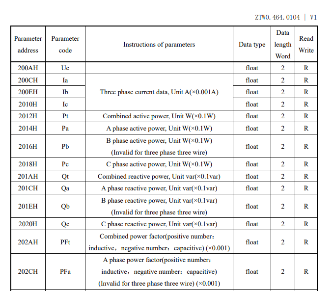
    Modbus is a widely adopted standard for data transmission between machines, which enables the standardised exchange of information through simple frames. The most important concept of this protocol is that all variables read and written are stored in so-called registers. Registers have different types and addresses, which can be found in the documentation. From the table below, we can see that, for example, phase voltages start at register 0x200A, are 32-bit (2 registers) and are of type float, i.e. floating-point.
    The DTSU666 bidirectional, three-phase electricity meter and data retrieval via Modbus on the ESP32
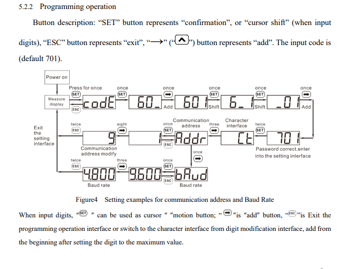
    RS485 can operate with various port and baud rate settings, whilst Modbus supports various slave IDs. These settings must match between the meter and the firmware. On the meter, they can be changed via the UI:
    The DTSU666 bidirectional, three-phase electricity meter and data retrieval via Modbus on the ESP32
    Now you’ll need the firmware. The simplest way is probably to write it in PlatformIO, which is an extension for the Visual Studio Code environment. It makes it easier to manage external libraries and automates the download of the appropriate compilers for our board. The project configuration is saved in its entirety in a single platformio.ini file, which greatly simplifies transferring code between different computers.
    I started with the basics, namely setting up over-the-air (OTA) programming and a simple website:
    How to programme the Arduino-style Wemos D1 (ESP8266) board? ArduinoOTA in PlatformIO
    Next, I added the ModbusMaster library to the project:
    https://github.com/4-20ma/ModbusMaster
    My platformio.ini:
    Code: Ini
    Log in, to see the code

    With the library now added to the project, querying the meter is essentially just a matter of calling a single function. Below is a short code snippet showing how to read the 32-bit voltage value for phase L1 (address 0x2006). Please note that after a successful read, we need to combine two 16-bit registers into a single
    float
    and divide the result by 10 – exactly as required by the manufacturer’s documentation.
    Code: C / C++
    Log in, to see the code

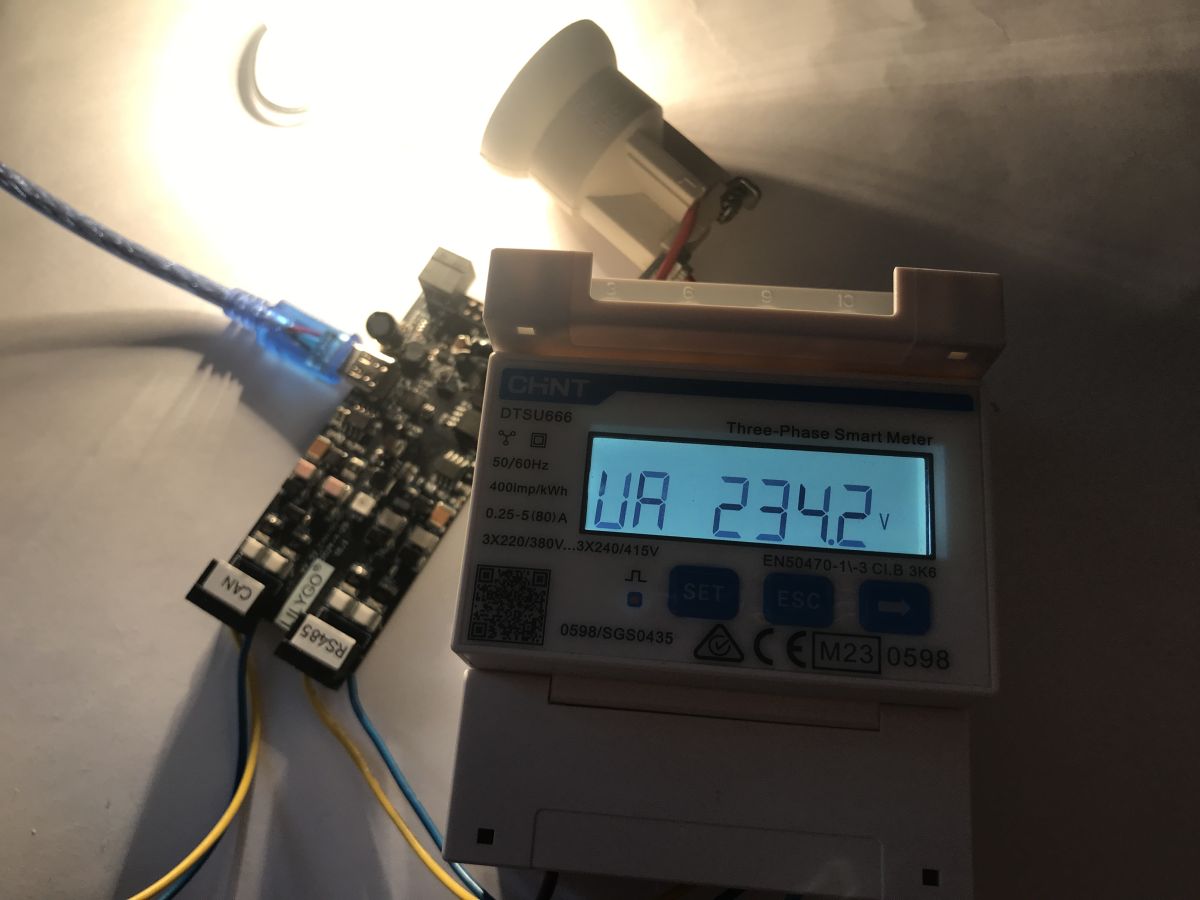
    The whole process during testing:
    The DTSU666 bidirectional, three-phase electricity meter and data retrieval via Modbus on the ESP32
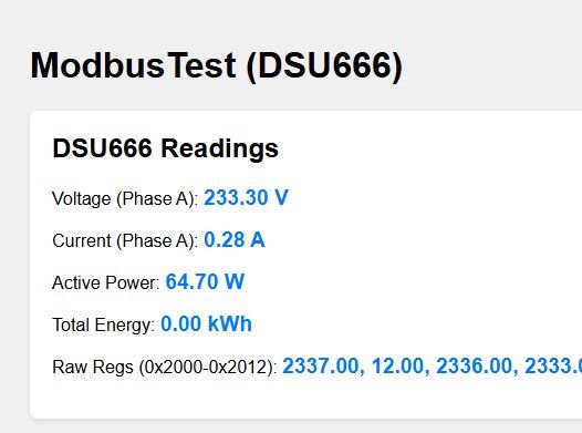
    Results on the web:
    The DTSU666 bidirectional, three-phase electricity meter and data retrieval via Modbus on the ESP32
    In the same way, you can access other values from the documentation, such as phase current (from 0x200C), total active power (0x2012), power factor (0x202A), total energy consumed and supplied (from 0x101E) or even the mains frequency (0x2044).

    Full register table:
    Address Code Parameter description Data type Length (words) Read/Write
    0000H REV. Software version Signed 1 R
    0001H UCode Programming code (1–9999) Signed 1 R/W
    0002H CLr.E Energy reset (1: clear energy) Signed 1 R/W
    0003H net Selection of mains configuration (0: 3-phase 4-wire, 1: 3-phase 3-wire) Signed 1 R/W
    0006H IrAt Current ratio (1–9999) Signed 1 R/W
    0007H UrAt Voltage ratio (0.1–999.9) Signed 1 R/W
    000AH Disp Alternating display time (s) Signed 1 R/W
    000BH B.LCD Screen backlight duration (minutes) Signed 1 R/W
    000CH Endian Reserved Signed 1 R/W
    002CH Protocol Protocol selection (1: DL/T645, 2:n.2, 3:n.1, 4:E.1, 5: o.1) Signed 1 R/W
    002DH bAud Transmission speed (0:1200, 1:2400, 2:4800, 3:9600) Signed 1 R/W
    002EH Addr Modbus address (1–247) Signed 1 R/W
    2000H Uab Phase-to-phase voltage Uab (V, ×0.1) float 2 R
    2002H Ubc Ubc phase-to-phase voltage (V, ×0.1) float 2 R
    2004H Uca Phase-to-phase voltage Uca (V, ×0.1) float 2 R
    2006H Ua Phase voltage Ua (V, ×0.1) float 2 R
    2008H Ub Phase voltage Ub (V, ×0.1) float 2 R
    200AH Uc Phase voltage Uc (V, ×0.1) float 2 R
    200CH Ia Phase A current (A, ×0.001) float 2 R
    200EH Ib Phase B current (A, ×0.001) float 2 R
    2010H Ic Phase C current (A, ×0.001) float 2 R
    2012H Fri Total active power (W, ×0.1) float 2 R
    2014H Pa Active power, phase A (W, ×0.1) float 2 R
    2016H Pb Active power, phase B (W, ×0.1) float 2 R
    2018H Pc Active power, phase C (W, ×0.1) float 2 R
    201AH Qt Total reactive power (var, ×0.1) float 2 R
    201CH Qa Reactive power, phase A (var, ×0.1) float 2 R
    201EH Qb Reactive power, phase B (var, ×0.1) float 2 R
    2020H Qc Reactive power, phase C (var, ×0.1) float 2 R
    202AH PFt Total power factor (×0.001) float 2 R
    202CH PFa Phase A power factor (×0.001) float 2 R
    202EH PFb Phase B power factor (×0.001) float 2 R
    2030H PFc Phase C power factor (×0.001) float 2 R
    2044H Freq Mains frequency (Hz, ×0.01) float 2 R
    101EH ImpEp Total active energy consumed (kWh) float 2 R
    1020H ImpEpA Active energy consumed, phase A (kWh) float 2 R
    1022H ImpEpB Active energy consumed, phase B (kWh) float 2 R
    1024H ImpEpC Active energy consumed, phase C (kWh) float 2 R
    1026H NetImpEp Net active energy consumed (kWh) float 2 R
    1028H ExpEp Total active energy supplied (kWh) float 2 R
    102AH ExpEpA Active energy supplied, phase A (kWh) float 2 R
    102CH ExpEpB Active energy supplied, phase B (kWh) float 2 R
    102EH ExpEpC Active energy supplied, phase C (kWh) float 2 R
    1030H NetExpEp Net active energy supplied (kWh) float 2 R

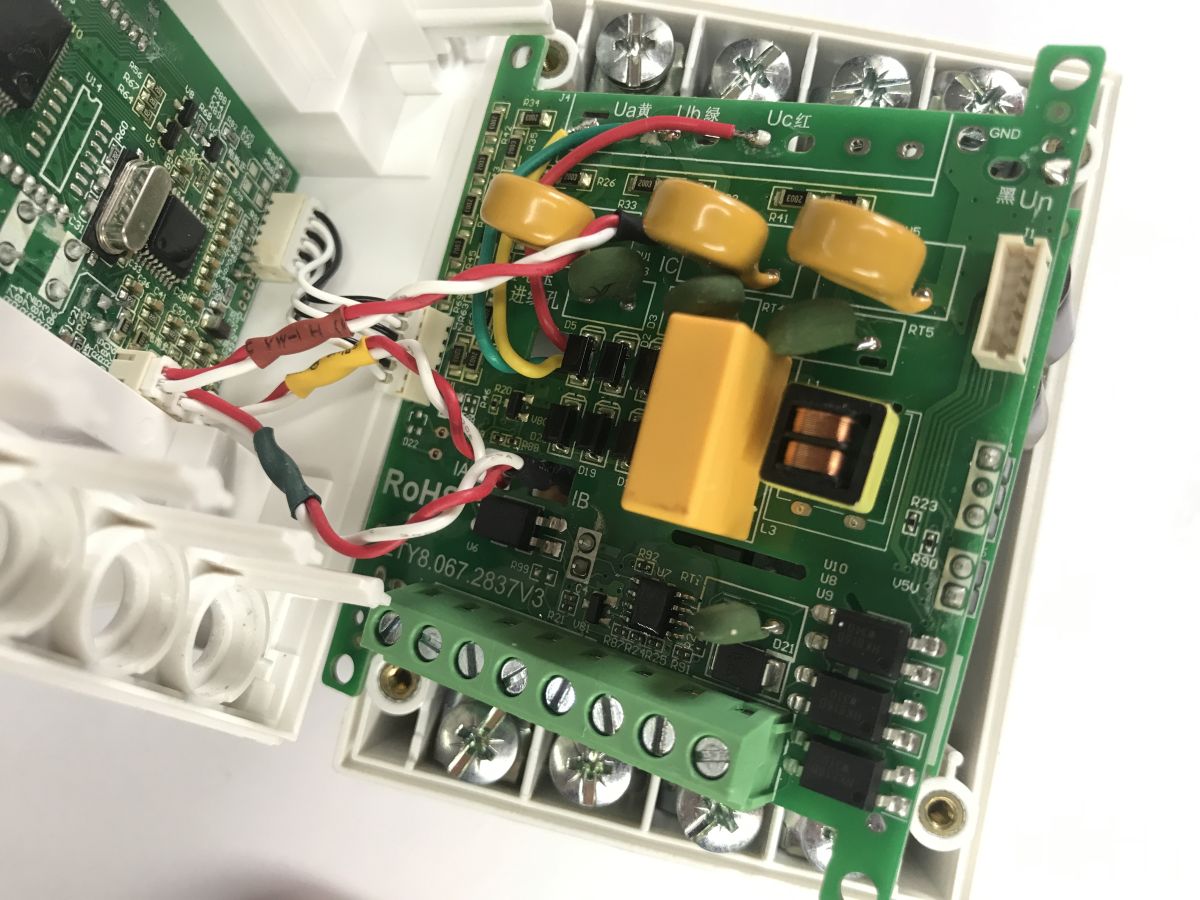
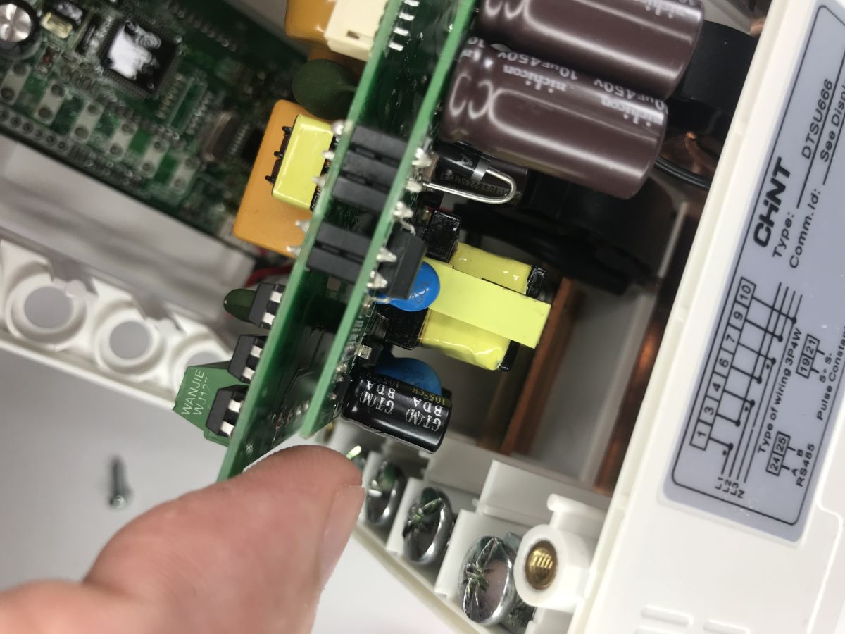
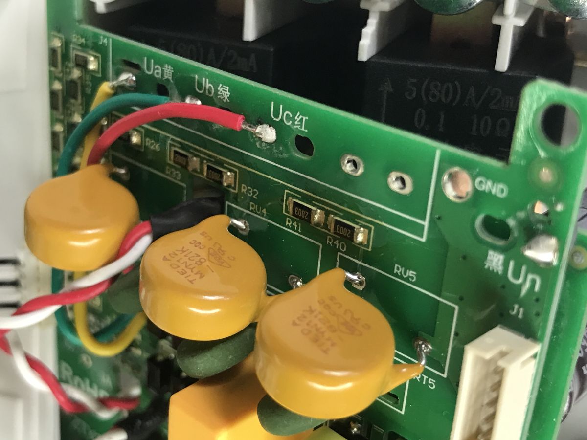
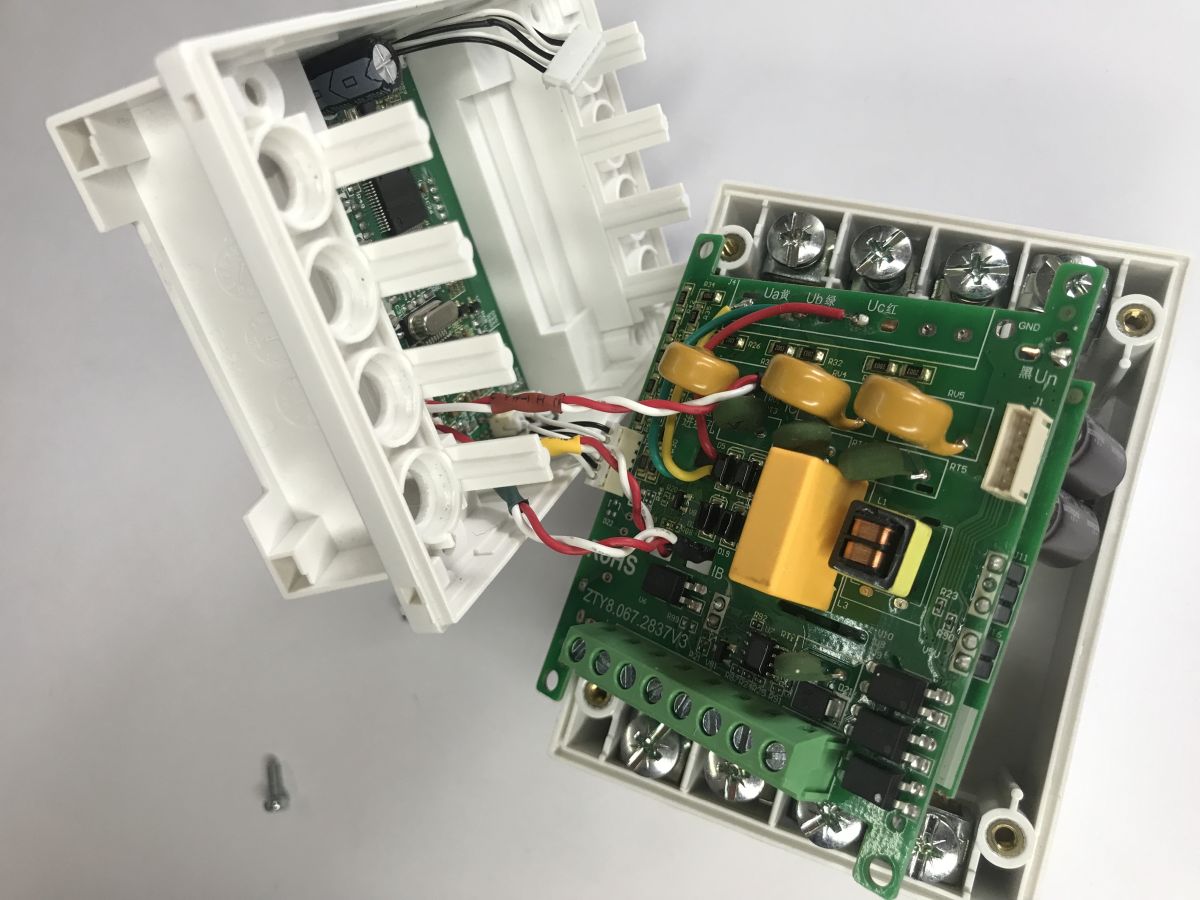
    You can also take a look inside the meter:
    The DTSU666 bidirectional, three-phase electricity meter and data retrieval via Modbus on the ESP32 The DTSU666 bidirectional, three-phase electricity meter and data retrieval via Modbus on the ESP32 The DTSU666 bidirectional, three-phase electricity meter and data retrieval via Modbus on the ESP32 The DTSU666 bidirectional, three-phase electricity meter and data retrieval via Modbus on the ESP32 The DTSU666 bidirectional, three-phase electricity meter and data retrieval via Modbus on the ESP32
    The integrated circuits are unmarked; the board is coated with a layer of varnish for protection. The internal layout appears to be quite elaborate; MYN12-821K varistors can be seen, used for surge protection, along with 5(80)A\2mA current transformers.

    In summary, integrating the DTSU666 meter into your own projects relies on handling standard serial communication via an RS485 converter. Thanks to the libraries available for the ESP32, we can handle the Modbus RTU protocol by calling a single function. This enables automated monitoring of network parameters without being locked into a single manufacturer’s closed software ecosystem. We can now freely process the received data and send it on to a display, a database, or perhaps even to Home Assistant.
    Do you use energy meters with a Modbus interface?

    Cool? Ranking DIY
    Helpful post? Buy me a coffee.

    About Author
    p.kaczmarek2
    Moderator Smart Home
    Offline 
    p.kaczmarek2 wrote 14803 posts with rating 12965, helped 659 times. Been with us since 2014 year.
  • ADVERTISEMENT
  • Python Modbus RTU example for DTSU666 registers

    #2 21941796
    rezydent1
    Level 15  
    Posts: 279
    Help: 2
    Rate: 155
    This is what it would look like in Python (I don’t have a meter, so I can’t check 100%)
    Programme functions:

    Reading all parameters – read_all_data()

    Reading selected parameters – read_specific_data(['Ia', 'Ib', 'Ic'])

    Continuous reading – uncomment the section in
    main()
    for reading in a loop

    Formatted output – clear display of data with units

    Notes on communication:

    The DTSU666 uses 2 registers (4 bytes) for float-type data

    Values are scaled as per the documentation (×0.001A, ×0.1W, etc.)

    Power factor: positive = inductive, negative = capacitive

    #!/usr/bin/env python3
    """
    Program do odczytu danych z miernika energii elektrycznej DTSU666 przez Modbus RTU
    Wykorzystuje bibliotekę minimalmodbus
    """
    
    import minimalmodbus
    import time
    import sys
    import logging
    
    # Konfiguracja logowania
    logging.basicConfig(level=logging.INFO, format='%(asctime)s - %(levelname)s - %(message)s')
    logger = logging.getLogger(__name__)
    
    class DTSU666:
        """Klasa do obsługi miernika DTSU666 przez Modbus RTU"""
    
        def __init__(self, port='/dev/ttyUSB0', slave_address=1, baudrate=9600, timeout=1):
            """
            Inicjalizacja połączenia z miernikiem
    
            Args:
                port: Port szeregowy (np. '/dev/ttyUSB0', 'COM3')
                slave_address: Adres Modbus urządzenia (domyślnie 1)
                baudrate: Prędkość transmisji (domyślnie 9600)
                timeout: Timeout w sekundach
            """
            self.port = port
            self.slave_address = slave_address
            self.baudrate = baudrate
            self.timeout = timeout
    
            # Inicjalizacja instrumentu Modbus
            self.instrument = minimalmodbus.Instrument(port, slave_address)
            self.instrument.serial.baudrate = baudrate
            self.instrument.serial.bytesize = 8
            self.instrument.serial.parity = minimalmodbus.serial.PARITY_NONE
            self.instrument.serial.stopbits = 1
            self.instrument.serial.timeout = timeout
    
            # Ustawienie trybu komunikacji (RTU)
            self.instrument.mode = minimalmodbus.MODE_RTU
    
            # Mapowanie rejestrów z dokumentacji
            self.registers = {
                'Uc': {'address': 0x200A, 'name': 'Napięcie fazy C', 'unit': 'V', 'scale': 0.001},
                'Ia': {'address': 0x200C, 'name': 'Prąd fazy A', 'unit': 'A', 'scale': 0.001},
                'Ib': {'address': 0x200E, 'name': 'Prąd fazy B', 'unit': 'A', 'scale': 0.001},
                'Ic': {'address': 0x2010, 'name': 'Prąd fazy C', 'unit': 'A', 'scale': 0.001},
                'Pt': {'address': 0x2012, 'name': 'Moc czynna całkowita', 'unit': 'W', 'scale': 0.1},
                'Pa': {'address': 0x2014, 'name': 'Moc czynna fazy A', 'unit': 'W', 'scale': 0.1},
                'Pb': {'address': 0x2016, 'name': 'Moc czynna fazy B', 'unit': 'W', 'scale': 0.1},
                'Pc': {'address': 0x2018, 'name': 'Moc czynna fazy C', 'unit': 'W', 'scale': 0.1},
                'Qt': {'address': 0x201A, 'name': 'Moc bierna całkowita', 'unit': 'var', 'scale': 0.1},
                'Qa': {'address': 0x201C, 'name': 'Moc bierna fazy A', 'unit': 'var', 'scale': 0.1},
                'Qb': {'address': 0x201E, 'name': 'Moc bierna fazy B', 'unit': 'var', 'scale': 0.1},
                'Qc': {'address': 0x2020, 'name': 'Moc bierna fazy C', 'unit': 'var', 'scale': 0.1},
                'Pft': {'address': 0x202A, 'name': 'Współczynnik mocy całkowity', 'unit': '', 'scale': 0.001},
                'Pfa': {'address': 0x202C, 'name': 'Współczynnik mocy fazy A', 'unit': '', 'scale': 0.001},
            }
    
            logger.info(f"Zainicjalizowano DTSU666 na porcie {port}, adres: {slave_address}, baudrate: {baudrate}")
    
        def read_float(self, register_address, scale=1.0):
            """
            Odczyt wartości zmiennoprzecinkowej z rejestru
    
            Args:
                register_address: Adres rejestru (hex)
                scale: Współczynnik skali
    
            Returns:
                float: Odczytana wartość
            """
            try:
                # Odczyt 2 rejestrów (4 bajty) jako float
                value = self.instrument.read_float(register_address, 3, 2)
                return value * scale
            except Exception as e:
                logger.error(f"Błąd odczytu rejestru 0x{register_address:04X}: {e}")
                return None
    
        def read_all_data(self):
            """
            Odczyt wszystkich dostępnych danych z miernika
    
            Returns:
                dict: Słownik z odczytanymi wartościami
            """
            data = {}
    
            logger.info("Rozpoczynanie odczytu danych z DTSU666...")
    
            for key, reg_info in self.registers.items():
                address = reg_info['address']
                scale = reg_info['scale']
                name = reg_info['name']
                unit = reg_info['unit']
    
                value = self.read_float(address, scale)
    
                if value is not None:
                    data[key] = value
                    # Wyświetlenie odczytanej wartości
                    if unit:
                        logger.info(f"{name}: {value:.3f} {unit}")
                    else:
                        logger.info(f"{name}: {value:.3f}")
                else:
                    data[key] = None
                    logger.warning(f"Nie udało się odczytać {name}")
    
            return data
    
        def read_specific_data(self, parameters):
            """
            Odczyt wybranych parametrów
    
            Args:
                parameters: Lista nazw parametrów do odczytu
    
            Returns:
                dict: Słownik z odczytanymi wartościami
            """
            data = {}
    
            for param in parameters:
                if param in self.registers:
                    reg_info = self.registers[param]
                    value = self.read_float(reg_info['address'], reg_info['scale'])
    
                    if value is not None:
                        data[param] = value
                        logger.info(f"{reg_info['name']}: {value:.3f} {reg_info['unit']}")
                    else:
                        data[param] = None
                        logger.warning(f"Nie udało się odczytać {reg_info['name']}")
                else:
                    logger.error(f"Nieznany parametr: {param}")
                    data[param] = None
    
            return data
    
        def format_output(self, data):
            """
            Formatowanie danych do czytelnego wyjścia
    
            Args:
                data: Słownik z danymi
    
            Returns:
                str: Sformatowany string
            """
            output = []
            output.append("=" * 60)
            output.append(f"DTSU666 - Odczyt danych z {time.strftime('%Y-%m-%d %H:%M:%S')}")
            output.append("=" * 60)
    
            for key, value in data.items():
                if key in self.registers and value is not None:
                    reg_info = self.registers[key]
                    name = reg_info['name']
                    unit = reg_info['unit']
                    output.append(f"{name:30}: {value:>10.3f} {unit}")
                elif key in self.registers:
                    output.append(f"{self.registers[key]['name']:30}: {'BRAK DANYCH':>10}")
    
            output.append("=" * 60)
            return "\n".join(output)
    
    
    def main():
        """Funkcja główna"""
    
        # Konfiguracja połączenia - dostosuj do swojego systemu
        # Linux: /dev/ttyUSB0 lub /dev/ttyS0
        # Windows: COM1, COM2, itp.
        PORT = '/dev/ttyUSB0'  # Zmień na odpowiedni port
        SLAVE_ADDRESS = 1       # Adres Modbus miernika (domyślnie 1)
        BAUDRATE = 9600         # Prędkość transmisji
    
        # Utworzenie instancji miernika
        meter = DTSU666(port=PORT, slave_address=SLAVE_ADDRESS, baudrate=BAUDRATE)
    
        try:
            # Pojedynczy odczyt wszystkich danych
            logger.info("=== POJEDYNCZY ODCZYT WSZYSTKICH DANYCH ===")
            data = meter.read_all_data()
            print(meter.format_output(data))
    
            # Przykład odczytu wybranych parametrów
            logger.info("\n=== ODCZYT WYBRANYCH PARAMETRÓW ===")
            selected_params = ['Uc', 'Ia', 'Ib', 'Ic', 'Pt', 'Pft']
            selected_data = meter.read_specific_data(selected_params)
            print(meter.format_output(selected_data))
    
            # Przykład ciągłego odczytu (odkomentuj jeśli potrzebujesz)
            """
            logger.info("\n=== ROZPOCZYNAMNIE CIĄGŁEGO ODCZYTU (Ctrl+C aby zatrzymać) ===")
            while True:
                try:
                    data = meter.read_all_data()
                    print(meter.format_output(data))
                    print("\n" + "-" * 60)
                    time.sleep(2)  # Odczyt co 2 sekundy
                except KeyboardInterrupt:
                    logger.info("Zatrzymano przez użytkownika")
                    break
                except Exception as e:
                    logger.error(f"Błąd podczas ciągłego odczytu: {e}")
                    time.sleep(5)
            """
    
        except Exception as e:
            logger.error(f"Błąd główny: {e}")
            return 1
    
        return 0
    
    
    if __name__ == "__main__":
        # Sprawdzenie czy biblioteka minimalmodbus jest zainstalowana
        try:
            import minimalmodbus
        except ImportError:
            print("Brak biblioteki minimalmodbus. Instaluj: pip install minimalmodbus")
            sys.exit(1)
    
        sys.exit(main())
    
  • ADVERTISEMENT
  • Modbus register decoding requires float conversion and divide by 10

    #3 21942381
    CosteC
    Level 39  
    Posts: 5394
    Help: 405
    Rate: 1679
    Just a few minor points:
    - This is an active power meter. It is not a reactive power meter, and there is no relevant standard as mentioned. It’s good that it has some records relating to reactive power, but the accuracy of reactive power measurement is arbitrary.
    - The accuracy of active power measurements is 1%.
    - The IP54 rating looks like complete nonsense – splashes will allow water to get inside and cause corrosion. It’s good that there’s a coating on the PCBA, but it’s a shame the board wasn’t cleaned before coating. I don’t know how on earth this is supposed to meet IP54.
    - The insulation clearances appear to be rated for a maximum of CAT III 300V, meaning it’s suitable at most as a sub-meter with additional surge protection.

    p.kaczmarek2 wrote:
    Please note that after successful reception, we need to combine two 16-bit registers into a single floating-point number and divide the result by 10 – exactly as required by the manufacturer’s documentation.

    Well, that’s quite an approach. Having a floating-point format and still requiring division… What a pity.
  • Asking for a better Modbus meter recommendation

    #4 21942388
    p.kaczmarek2
    Moderator Smart Home
    Posts: 14803
    Help: 659
    Rate: 12965
    This is how it appears in the documentation – float type:
    Quote:

    Note 1: Single-precision floating point adopts the standard IEEE 754 format, totalling 32 bits (4 words). The
    single-precision floating point mode is assumed to be ABCD (high-order byte first, low-order
    byte last).

    The DTSU666 bidirectional, three-phase electricity meter and data retrieval via Modbus on the ESP32
    DTSU666 DS...Manual.pdf (1.15 MB)You must be logged in to download this attachment.

    @CosteC it seems you have a great deal of experience in this field. Could you recommend a better meter, also with a Modbus interface?
    Helpful post? Buy me a coffee.
  • Float type questioned for reactive power measurements

    #5 21942426
    CosteC
    Level 39  
    Posts: 5394
    Help: 405
    Rate: 1679
    p.kaczmarek2 wrote:
    It seems you have a lot of experience in this field.

    Thank you, but I don’t.

    I do have experience in looking for ‘marketing optimisations’ and in designing measuring devices, and therefore in their safety and compliance with standards. Thanks to elektodzie, I’ve become interested in how reactive power is measured. If a meter isn’t compliant with PN-EN IEC 62053-24:2021-05, it doesn’t measure reactive power in a way that a distribution system operator (DSO) such as Tauron will accept.

    Can this meter measure correctly? Yes, it can. Will the energy supplier accept such measurements? No, because there is no basis for accepting them.
    p.kaczmarek2 wrote:
    That’s what it says in the documentation – type float:

    I KNOW! I just don’t understand WHY they’d do this. To the best of my knowledge, it doesn’t improve either the resolution or the accuracy. The range of a 32-bit FLOAT also comfortably covers the voltages and currents (in SI units) for such a meter, so WHY was this done? If it’s down to incompetence, I have serious concerns about the quality of this instrument.
  • #6 21942429
    xury
    Automation specialist
    Posts: 7085
    Help: 878
    Rate: 1498
    This distinction stems from the fact that the list of registers is virtually the same for through-type meters with a fixed ratio as for meters with CTs, where the result depends on the CT ratio. The higher the CT ratio, the lower the measurement accuracy.
  • ADVERTISEMENT
  • CT ratio should not reduce measurement accuracy

    #7 21942496
    CosteC
    Level 39  
    Posts: 5394
    Help: 405
    Rate: 1679
    xury wrote:
    This distinction stems from the fact that the list of registers is virtually identical for through-type meters with a fixed ratio and for meters with CTs, where the result depends on the transformer ratio.

    That makes no sense. The power measurements would also need to be scaled.
    A sensible system is sealed with the specified transformer parameters and measures the correct values.

    xury wrote:
    The higher the CT ratio, the lower the measurement accuracy.

    It makes absolutely no sense. Why on earth would that be the case?
    When measuring 100 A and when measuring 1 A, the resolution may differ, but the accuracy itself should remain the same.
  • ADVERTISEMENT
  • #8 21942525
    kozak 22
    Level 13  
    Posts: 138
    Rate: 145
    For example, Eastron SDM630 Modbus MID
  • DTSU666 scaling quirks and slow update rate

    #9 21942536
    xury
    Automation specialist
    Posts: 7085
    Help: 878
    Rate: 1498
    I’m not saying that the DTSU666 is a brilliant meter for 250 zł :)
    It’s exactly as you say – you scale the power, current, reactive power and other measurements, but once you’ve set the correct ratio for voltage and current, the display does it automatically – and that makes no sense, because the display shows one set of data from the register and another, and you have to scale them yourself.
    And you’re right about the accuracy – I misspoke (or rather, mistyped :D )
    The higher the current ratio, the less frequently the data is updated – not the accuracy.
    I’ve used transformers with CT ratios of 60 and 5, and with the 60 ratio, the energy consumption update was 12 times less frequent. That’s just the nature of this meter. Besides, the procedure for changing the address via Modbus is described incorrectly and imprecisely in the manual.
    I use Nodered for meter readings.
    Personally, I prefer the Polish MEW-01, which pleasantly surprised me with a difference of around 4 kWh per year compared to the PGE Gama350 meter. And it works via MQTT rather than Modbus. Admittedly, it doesn’t have MID certification, but that doesn’t bother me.
    Despite this, I believe the DTSU666 is better than the much more expensive Carlo Gavazzi EM340 used by Victron.
  • CT ratio affects update frequency, not accuracy

    #10 21942558
    CosteC
    Level 39  
    Posts: 5394
    Help: 405
    Rate: 1679
    xury wrote:
    The higher the current ratio, the less frequently the data is updated – not the accuracy.
    I’ve used transformers with CT ratios of 60 and 5, and with the 60 ratio, the energy consumption update was 12 times less frequent. That’s just the nature of this meter.

    WOW. That’s astonishing. I’ve no idea why that would be the case. The slow flashing is normal, because when measuring low currents, the power consumed increases slowly, but the readings are updated at fixed time intervals in accordance with the standard.
  • Sign-changing power causes bidirectional meter discrepancies

    #11 21952307
    markosik20
    Level 33  
    Posts: 2263
    Help: 208
    Rate: 147
    I’ve been using this meter for over half a year. If it operated as a unidirectional meter, its readings would be virtually indistinguishable from those of a certified meter. The problem arises when active power changes sign (fed into the grid / drawn from the grid), and the more frequently this happens, the greater the discrepancies between the meters (naturally, the certified meter underestimates the energy fed into the grid and overestimates the energy drawn from it). You just need to make sure that the power does not change sign on any of the phases, and the consumption readings will not differ from those of the certified meter. The only drawback is the reading from the frequency register (complete nonsense )
  • #12 21952393
    CosteC
    Level 39  
    Posts: 5394
    Help: 405
    Rate: 1679
    markosik20 wrote:
    If it were operating as a unidirectional circuit

    markosik20 wrote:
    You just need to ensure that the power does not change polarity on any of the phases

    markosik20 wrote:
    The only drawback is the reading from the frequency register (complete nonsense)

    So it doesn’t measure what it’s supposed to correctly, and it’s hard to trust it...
  • Meter accuracy depends on declared class and application

    #13 21952640
    markosik20
    Level 33  
    Posts: 2263
    Help: 208
    Rate: 147
    CosteC wrote:
    So it doesn’t measure what it’s supposed to correctly, and it’s hard to trust it...

    You can’t trust any devices at all, as this is a matter of human interaction :D . Measuring devices are required to fall within the accuracy class declared by the manufacturer. For one, Class A (formerly Class 2) is sufficient; for another, Class 0.2 will not be accurate enough. Given that the meter costs what it costs, one has to accept a lower level of accuracy, and in 99 per cent of cases, that will be perfectly adequate.
Listen:
ADVERTISEMENT