






Hello,
Based on the archives of this forum, I have drawn a wiring diagram of the lighting connection to the INT-ORS expanders in order to realise the possibility of controlling the lighting in the house:
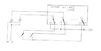
The expander controls 7 lighting circuits, the 8th output is used to switch off all circuits. The purpose is to achieve:
1. switching on and off the light with a standard switch.
2. switching off all circuits, e.g. when an alarm is activated.
3. to remotely switch on lights to simulate the presence of household members.
4. control of night-time, external lighting by means of e.g. movement detectors.
From the switch cabinet to the recessed contact box I lay a 5 x 1.5 mm cable, from the contact to the bulb at least 3 x 1.5 mm or more conductors for multi-circuit chandeliers. I make the connections in the contact box.
I have drawn a similar diagram for the control of external blinds:
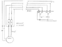
The installation requires laying 6 x 1.5mm cable to the cabinet and 4 x 1.5mm to the roller shutter. The connections also seem to be most conveniently made in the switch box.
I'm neither an electrician nor an automation technician, so I don't know what the advantages and disadvantages are of using satel expanders, or this solution, or whether it's OK. The advantage I notice is that you can always connect the wires in the switchboard and use the installation "classically".
Based on the archives of this forum, I have drawn a wiring diagram of the lighting connection to the INT-ORS expanders in order to realise the possibility of controlling the lighting in the house:
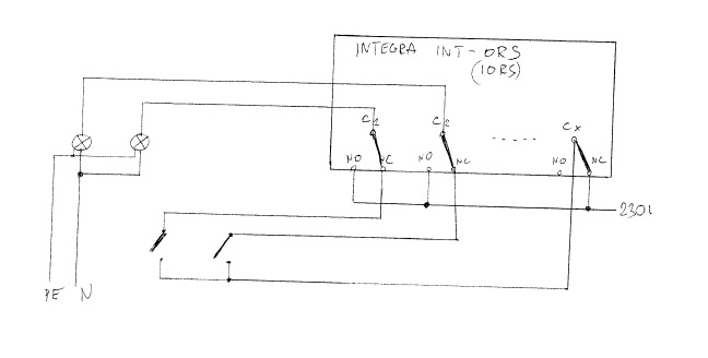
The expander controls 7 lighting circuits, the 8th output is used to switch off all circuits. The purpose is to achieve:
1. switching on and off the light with a standard switch.
2. switching off all circuits, e.g. when an alarm is activated.
3. to remotely switch on lights to simulate the presence of household members.
4. control of night-time, external lighting by means of e.g. movement detectors.
From the switch cabinet to the recessed contact box I lay a 5 x 1.5 mm cable, from the contact to the bulb at least 3 x 1.5 mm or more conductors for multi-circuit chandeliers. I make the connections in the contact box.
I have drawn a similar diagram for the control of external blinds:
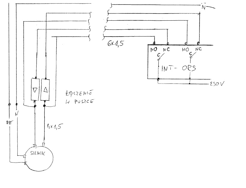
The installation requires laying 6 x 1.5mm cable to the cabinet and 4 x 1.5mm to the roller shutter. The connections also seem to be most conveniently made in the switch box.
I'm neither an electrician nor an automation technician, so I don't know what the advantages and disadvantages are of using satel expanders, or this solution, or whether it's OK. The advantage I notice is that you can always connect the wires in the switchboard and use the installation "classically".
