logo elektroda
logo elektroda
X
logo elektroda

How to connect the PCU-507 time relay correctly? No voltage on the contacts

Tomasz948 4014 9
Best answers LABEL_AI_GENERATED

How do I wire a PCU-507 time relay so the output contacts actually carry voltage?

The output contacts will not have voltage until you bridge the supply phase to the relay’s contact side; terminals 4 and 6 only power the timer itself, they do not feed the relay outputs [#14249838][#14249911] Connect the phase to the common contact terminal for the pole you use, i.e. 2 or 11 depending on which set of contacts you need, and take the switched output from the matching contact terminal [#14249838][#14249911] The red LED only shows that the relay has switched, not that the output contacts are already supplied with voltage [#14249838] Leave the 7–9 jumper set according to whether you want delayed switch-on or delayed switch-off [#14249838] Delayed switch-on means the timer counts down after power is applied and then energizes the relay, while delayed switch-off means the relay energizes immediately and stays on until the set time expires [#14252432]
AI summary based on the discussion. May contain errors.
ADVERTISEMENT
Treść została przetłumaczona polish » english Zobacz oryginalną wersję tematu
  • Seeking correct PCU-507 terminal wiring for output voltage

    #1 14249806
    Tomasz948
    Level 12  
    Posts: 109
    Rate: 3
    Hello,
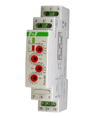
    I am a novice electrician and I have a problem with the correct connection of a relay,here a picture:
    How to connect the PCU-507 time relay correctly? No voltage on the contacts

    According to the instructions, the phase should be connected to terminal 4 and zero to 6
    On 7 and 9 we make a jumper, depending on whether we want delayed switch-on or switch-off.
    After the power supply there is no voltage on any of the contacts 1,2,3 and 10,11,12, even though the red diode indicates that the relay contacts are on.
    Can someone explain to me how to connect the relay correctly?
  • ADVERTISEMENT
  • #2 14249838
    nowy225
    Level 12  
    Posts: 31
    Help: 2
    Rate: 14
    Hi mate you need to connect terminal 4 to 2 or 11 as these are relays and have no connection to the power supply. Then it will connect to the contacts.
  • #3 14249859
    Tomasz948
    Level 12  
    Posts: 109
    Rate: 3
    oh i thought they were bridged in the middle
    Surely 6 and not 4? on 6 is neutral
  • ADVERTISEMENT
  • #4 14249911
    nowy225
    Level 12  
    Posts: 31
    Help: 2
    Rate: 14
    .Combine the phase with 2 or(i) 11 depending on how many contacts you use and internal connection is rare in timers.Sorry for the error.
  • ADVERTISEMENT
  • #5 14249933
    Tomasz948
    Level 12  
    Posts: 109
    Rate: 3
    sorry I messed up, that's right on 4, I looked wrong.
    And one more question, suppose I use an incandescent bulb as a receiver and now I connect it to let's say contact 3 and the zero of the bulb is put on 1 or the zero of the relay so on 6 ?
  • Clarifying zero versus neutral and network layout

    #6 14250104
    Akrzy74
    Rest in Peace
    Posts: 7910
    Help: 363
    Rate: 1504
    Tomasz948 wrote:
    and the zero of the bulb is given to 1 or the zero of the relay so to 6 ?

    Why at "zero" ? - in what grid system is the installation working?
    The zero conductor is not the same as the N conductor (different network layouts), so the information is important. If the esteemed author can't see the difference, I'll move to the "sandbox" section where, as someone wrote- "nobody knows anything and the level is the vestibule of the bin..."
  • #7 14250224
    Tomasz948
    Level 12  
    Posts: 109
    Rate: 3
    T-N-S, I colloquially wrote zero,it is about the neutral wire.
  • #8 14250262
    Akrzy74
    Rest in Peace
    Posts: 7910
    Help: 363
    Rate: 1504
    This is a technical forum- please stick to the correct nomenclature and do not mislead.
  • ADVERTISEMENT
  • #9 14250437
    Tomasz948
    Level 12  
    Posts: 109
    Rate: 3
    Still about this relay, what is the difference between delayed on and delayed off, so in practice.
  • #10 14252432
    nowy225
    Level 12  
    Posts: 31
    Help: 2
    Rate: 14
    Hi, delayed activation means that after applying voltage the timer counts down the preset time and activates the relay, and delayed deactivation means that after applying voltage the relay is immediately activated and remains activated until the preset time has elapsed.
ADVERTISEMENT