



logo elektroda
logo elektroda
X
logo elektroda

Where/how to power a Fibaro-style light switch module for motion sensors?

jareckib12 10020 13
Best answers

How can I power a wall switch module for motion-controlled lights when only the switched wire is available in the switch box?

You need a permanent supply in the switch box or an added junction box; if you only have the interrupted wire there, the practical options are to rewire for a proper L/N feed, use a two-wire dimmer with a bypass/capacitor, or place the control module in the distribution box instead [#14682268] [#14670240] [#14671872] Modern wiring runs a full three-wire cable to the switch box, with blue and yellow-green joined in Wago connectors and the phase switched by the wall switch [#14682268] If you want to power electronics without lighting the lamp, draw a tiny current through a small power supply in parallel with the switch and keep the lamp from glowing with a bypass capacitor across the light source [#14671872] Another suggestion was to avoid a relay entirely and use low-power parts, sleep modes, and energy storage such as a capacitor or supercapacitor [#14672815] The thread also notes that a custom battery-powered solution is possible if you use very low-voltage, low-current electronics, but it is more of a workaround than the preferred mains-powered fix [#14675378]
AI summary based on the discussion. May contain errors.
ADVERTISEMENT
This content has been translated flag-pl » flag-en View the original version here
  • #1 14670150
    jareckib12
    Level 10  
    Posts: 29
    Rate: 4
    Hi,
    By way of introduction:
    i got down to home automation, first of all z-wave and heating control. It works ok (server with Linux, Aeon z-stick , OpenHab previously, now Domoticz ) and developed a taste for more. Unfortunately the price of each piece averaged 150-200£. I did some research and found Mysensors - great stuff, everything can be done a few times cheaper. First sensors ready, even works :)

    To the shore:
    i have motion sensors and would like to control the lights with them - here comes the problem. Where do I get the power supply for the light switch? If I connect the power supply, after all, I will close the circuit and the bulb will light up :/ Well, and I can't control the relay, because by disconnecting I will lose power. On the other hand, I know that Fibaro has a dimmer module which somehow circumvents this problem and plugs in instead of a switch. It is even possible to buy a bypass to be able to control low power (LEDs) . I'm an amateur at electronics, but I suspect that the power circuit draws negligible current and closing the circuit does not cause the bulb to light up.
    Any ideas on how to solve this? Is it possible to make/buy such a power supply that would be plugged in series with the bulb and in parallel with the relay? Then a small current feeds the control circuit and the relay controls the bulb.

    In desperation, I was thinking about battery power, but while the temp sensor can be made to last six months/years, the relay draws a lot of current and won't last long on battery power. So how about a bistable relay controlled by 5V? Are there any? Although I would prefer to avoid battery power.

    Jarecki
  • ADVERTISEMENT
  • #2 14670240
    Anonymous
    Anonymous  
  • #3 14670276
    jareckib12
    Level 10  
    Posts: 29
    Rate: 4
    Well, yes it would be nice if I didn't have to rip up the walls for new cables for the switch. In the switch I only have the one, the blue one in your picture :(

    Jarecki
  • #4 14670305
    Anonymous
    Anonymous  
  • ADVERTISEMENT
  • #5 14670384
    jareckib12
    Level 10  
    Posts: 29
    Rate: 4
    Exactly not.
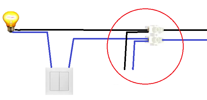
    The light circuit is made so that one wire goes from a switch box somewhere under the ceiling to the switch, from the switch to the light point and from the light point to the switch box. In the switch box I have one wire that is interrupted by a switch, so that I close the circuit and the bulb lights up.

    In practice this is done so that two wires go from the switch box to the switch and two from the switch box to the light, but the result is that we have a loop interrupted by the switch.

    To the best of my knowledge this is how it is done in the construction industry here in Poland (the so-called 2-wire system, here it is outlined ), although I may have outdated information and now pull two wires from the switch box to the switch and two wires from the switch to the point (3-wire). That would take care of the problem, but that is not the case with me unfortunately.

    This is with the rest of the problem in z-wave modules for lighting control. In Poland, only the dimmer from Fibaro works because it works with the 2-wire system, as I wrote in the first post. The rest require a 3-wire system, or are only suitable for sockets.

    Now I've thought about putting the control in a distribution box, but from such a box the wires extend to several points, so it would be impossible to stuff several control modules in there. So we are back to the initial question.

    Jarecki
  • #6 14670391
    maurycy123
    Conditionally unlocked
    Posts: 3117
    Help: 225
    Rate: 740
    machmichgut wrote:
    After all, the circuit has to be closed by a switch and so voltage comes through one
    And through the bulb. And the "N" will come from where?
  • #7 14670686
    Anonymous
    Anonymous  
  • #8 14670738
    750kV
    Level 33  
    Posts: 1936
    Help: 240
    Rate: 710
    machmichgut wrote:
    Luke-O, then why is the whole of my flat as I drew it and the installation was done by expert installers? Who is misleading whom here?

    If in your case the blue wire is interrupted by a switch, then either you have a phase on the blue - which is a reprehensible error, or the switch interrupts the N track - which is an even bigger error.
  • #9 14670772
    maurycy123
    Conditionally unlocked
    Posts: 3117
    Help: 225
    Rate: 740
    machmichgut wrote:
    Luke-O, then why is the whole of my flat as I drew it and the installation was done by expert installers? Who is misleading whom here?


    You have been misled.
    Wire colours:
    1. Brown and black are "phase" (L).
    2. Blue is "neutral" (N).
    3. Yellow and green is 'protective' (PE).

    In addition, the "phase" should be connected to the bottom of the bulb (via the switch) and the "neutral" to the thread (permanently).
    Any further questions?
  • ADVERTISEMENT
  • #10 14671872
    freebsd
    Level 42  
    Posts: 6791
    Help: 766
    Rate: 2032
    You have two states:

    I) Switch disconnected (light off).
    In the switch box you have power available and two problems. The first is that the voltage is reduced by a small size power supply. You can solve this analogously as given in II (in parallel with the switch) plus a current limiting resistor. The second problem is to make the current flow through the light source not cause it to glow or flash. This is where the bypass mentioned in #1, i.e. a capacitor connected in parallel with the light source, can help. I would also limit the current drawn and use a capacitor or supercapacitor as energy storage.

    II) Switch on (light on).
    You can gain a few volts from the voltage drop e.g. on diodes switched in series with the switch, as here:
    Light switch - how to make an indication that it is on

    The relay draws a few milliamps. Perhaps it would be better to replace it with a solid state component?
  • #11 14672724
    jareckib12
    Level 10  
    Posts: 29
    Rate: 4
    Is it possible to draw up a diagram? I can't do it myself, I don't know what values to give and what types of components.

    Jarecki
  • #12 14672815
    freebsd
    Level 42  
    Posts: 6791
    Help: 766
    Rate: 2032
    What voltage and amperage do you need to power the circuit? What light source will you be driving?

    Before you write, think about eliminating the relay, using low-voltage and energy-saving components, sleep modes, etc. How about using some kind of energy storage, such as a capacitor (supercapacitor) for increased energy demand (switching of the control element, wireless communication)? I would remind you that the current consumed by the control system has a direct impact on possible problems with e.g. LED lights - hence the need for "bypasses".
    All components must fit into a limited space. It is also necessary to keep the right distances and use components with the right parameters - so that there is no overvoltage.

    Some, or all, of the components will operate at a potential to earth close to the mains voltage. You wrote that you have already made sensors - I took this to mean that you have a good "feel" for electronics. Are you sure you want to make such a controller yourself? But maybe in this particular case it would be simpler to buy a ready-made one (little space, high voltage)?
  • ADVERTISEMENT
  • #13 14675378
    jareckib12
    Level 10  
    Posts: 29
    Rate: 4
    This got me thinking and I came to the conclusion that if there is no ready-made solution (or there is, but expensive - Fibaro dimmer £300!), then making my own might work out, but the size will be large.

    So I'm back to the battery idea. I did a bit of research and it turned out that the Arduino Pro Mini, when the clock is lowered, can be powered up to 1.8V, which works nicely because the radio module also works up to that voltage. Then a dormant Arduino with the power led and regulator removed draws 6uA, the radio module also some small amount. Tested and it came out at 1% off two AA batteries after 43 days, so it's good.

    Now the question of the relay. Are there any that are powered by low voltage so you don't have to give a step-up converter? And it has to be bistable, unless SSR relays take very little current to hold their state, or some other relay I don't know.

    Jarecki
  • #14 14682268
    retrofood
    VIP Meritorious for electroda.pl
    Posts: 31317
    Help: 1140
    Rate: 4791
    Unfortunately, if the installation is done by amateurs, this is the result.
    Modern installations are carried out by running a full three-wire power cable to the light switch box and leading either a three-wire or four-wire cable out of it as required.
    The blue and yellow-green wires are connected respectively with wago connectors at the bottom of the box, while the phase wires are short-circuited by the switch. Any switch.
    In this way we always have access to a full, safe power supply in the breaker box.
ADVERTISEMENT