logo elektroda
logo elektroda
X
logo elektroda

[Solved] Thrustmaster TX Steering Wheel: Identifying 3.3v Voltage Regulator on Board & Power Supply Info

purejoy88 24576 19
ADVERTISEMENT
Treść została przetłumaczona polish » english Zobacz oryginalną wersję tematu
  • #1 15512475
    purejoy88
    Level 10  
    Hello

    I am looking for a diagram or at least information on what regulates the 3.3 V voltage supplying the main circuits in the Thrustmaster TX steering wheel board.
    The board has a 24V power supply (mainly for motor power), which is activated when the USB cable is connected (by sending 5V to the power supply).
    I found one DC-DC regulator (TPS54040) on the board, which reduces the voltage to 12 V to power the cooling fan. I suspect that from the same 24V line, or from the mentioned 12V, the voltage is reduced to 3.3V, but I have no idea where. Have any of you had any experience with this board?

    Currently, after connecting the USB to the computer, the voltage on the systems slowly increases to 0.4 V. I don't think so. that 3.3V is obtained from 5V from USB - a friend who has a working T500RS (very similar in construction) - when connecting only USB without the power supply, the steering wheel is not even detected.

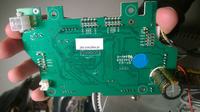
    I connected an external 3.3 V power supply to one of the capacitors of the power supply line (the one in the orange frame in the picture) and the steering wheel came to life - the PC detected it correctly, the motor turned a little, so the control should also be ok. The steering wheel was detected, I even managed to update the firmware but the steering wheel position sensor (AS5048A) and none of the buttons work. The 3.3 V that I connected also reaches the sensor and is consistent with its data sheet.
    I wonder if such an external power connection does not cause another problem that makes the signals not detected by the main cube. So I wanted to start by fixing the 3.3V power supply.

    The board itself is based on the TM4C123GE6PZ cube, plus the DRV8301 brushless motor driver - both powered from 3.3 V.
    There is one chip that I can't identify - on the housing there is something like this: 35901 74203 he327 and it has 10 pins - do you know what it could be?

    Pictures below, thanks in advance for your help.
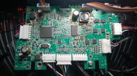
    Thrustmaster TX Steering Wheel: Identifying 3.3v Voltage Regulator on Board & Power Supply Info Thrustmaster TX Steering Wheel: Identifying 3.3v Voltage Regulator on Board & Power Supply Info
  • ADVERTISEMENT
  • Helpful post
    #2 15580915
    Fikszyn
    Level 19  
    The voltage of 3.3 V is implemented by the DRV8301 driver. Check the D1 diode (Schottky diode, you marked it in the orange area), but also the FB35 and FB36 protections (this one looks like a smd transistor, it is a fast diode, 1N4848 can be used) lower left corner of photo 1.
    And by the way, if you had damaged mosfets, then DRV should be replaced - the cause of engine damage, magnet stator peeled off. The systems receive incorrect information from the hallotron, and the hallotron from the motor in which the stator has moved. This information goes to the system, which states that there is too little current on the motor and a disaster, mosfets fly, often DRV.
    Thrustmaster TX Steering Wheel: Identifying 3.3v Voltage Regulator on Board & Power Supply Info
  • #3 15584291
    ras2375
    Level 2  
    I am struggling with the T300 steering wheel, practically mechanically new. First it disconnected during autocalibration. The reason was a cold solder on one of the transistors, the impact caused the power supply to turn off, as the 5V from the USB disappeared. Then the steering wheel was not recognized by the PC as T300RS, here the reason was a bad contact on the PS4 / PS3 switch. After a week of use, the steering wheel began to lose force feedback and had problems with autocalibration. Calibrating the engine with Thrustmaster's software restored it to working order for about 20 minutes of playing. Then the steering wheel decided to "turn on the green light" and not be recognized by the PC - here the 6 MHz crystal failed. Now the steering wheel goes about 4 minutes properly, then the FFB weakens. I noticed that the resistance on the turning angle limits, especially to the left, decreases. After a few gentle turns on the left extreme position (as if you were pumping), the resistance force returns to normal and the steering wheel works for about 3-5 minutes. After this pumping procedure, there is also no problem with autocalibration. You think that the motor may also be damaged here, or something with the communication between DRV8301 (I mean voltage sense or Isense) and TM4C123g, because here the motor control is probably in a sensorless system - as it is compared with the AS5048A rotation angle sensor at the end of the motor ? I have no idea whether to look for the cause in the engine or in the electronics? Maybe you have some more experience with this Chinese dud?
  • #4 15598880
    purejoy88
    Level 10  
    @Fikszyn - thanks for the tip. I desoldered and checked the D1 diode some time ago - it's ok. From which leg of this driver is this voltage taken - from No. 23 (the data sheet says that it should not be used to power other systems, besides I do not see the connection)?
    In the meantime, due to the problems with the lack of signals reaching the cube (buttons and the position of the wheel / pedal) - I ordered a new plate from Thrustmaster (which cost me 69 euros with shipping - considering that I bought the steering wheel for 150 PLN, I am still forward).
    I checked the motor earlier - I measured the resistance on each winding (equal) and the voltage that is induced after connecting it to the drill and turning the rotor. I didn't feel much resistance when turning the engine, so I assumed it was working.
    When I bought this steering wheel (as damaged), DRV8301 was desoldered from the plate - that is, someone had already fought with it before, but gave up. After soldering the new driver, I had the problem described in the first post.

    In any case, now the steering wheel works on a new board - while the old one will be left as spare parts. Thanks for the help.

    ras2375 - if it spins your engine during calibration, the engine is ok. It's strange that the steering wheel "weaks" only after some time of playing. Does your voltage drop after a while? - maybe the power supply is to blame. If, as you say, you "pump" the steering wheel - then maybe in this way you recharge the capacitors for a while (although I do not know if it is possible) and then it works again for a while (to discharge).
    Look for the "Andrew Daniels TX Thread" guide on the isrtv.com forum - if it is indeed the power supply - maybe the replacement that Andrew proposed for the TX will fit the T300RS (in fact, they are the same steering wheels).
  • ADVERTISEMENT
  • #5 15599669
    ras2375
    Level 2  
    @purejoy88 - thanks for your interest, indeed with a weak FFB power, the voltage on the power supply when trying to break the resistance drops to 22 V. In general, it varies between 22 V and 32 V. I checked the workshop power supply and it happens the same, the current consumption increases to 2, 7 A. The motor reaches a temperature of 33 degrees on the heatsink. The fan turns on pretty quickly. When it was working properly, the fan would turn on after 15 minutes and now it turns on even after 30 seconds. I haven't measured the motor yet, but mechanically it spins smoothly. How did you buy the disc from Thrustmaster? Can you buy spare parts from them?
  • ADVERTISEMENT
  • #6 15610644
    purejoy88
    Level 10  
    The behavior of the power supply seems to be ok - a difficult thing, nothing else comes to mind. Did you just turn the engine or the steering wheel? Maybe there is some resistance on the gearbox / bearing of the axle itself, which causes the engine to overheat.
    As for the new pbc - you have to write through the official support at:
    https://ts.thrustmaster.com
    Officially, there is no such spare part and they are not willing to ship them. Only when I described to them a few cases where I had information from several forums that they offered such a replacement - they agreed to send it on the condition that I agree that I will not receive any instructions on how to replace the board and I acknowledge that I am not entitled to any warranty.
  • #7 15623810
    Fikszyn
    Level 19  
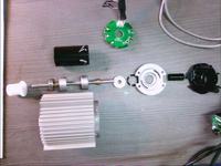
    There is a problem with the motor that after calibration it worked properly, but during playing and strong hits to the limit switches the magnetic core of the motor is shifted. This is the black shaft in the photo, it is mounted on an axle with aluminum spacers, see photo. It is glued, but under the influence of temperature and impacts it peels off and moves, it starts to react incorrectly in games. Out of 50 pieces, 70% had the core peeled off.
  • #8 15625521
    ras2375
    Level 2  
    In fact, the engine is not of the highest quality. I suspected that the stator was moving in the housing, but as you can see from your experience, the magnet is to blame. In fact, the motor works the hardest when it is stopped (current consumption from the power supply above 2 A) and then it loses synchronization very quickly, starts to heat up and loses power. When I move it to the lock point of the set angle limiter, the current consumption increases. When I hold it like that for a while, the current drops and the motor regains power, synchronization returns and everything is ok for a while. It has nothing to do with lowering the power by the microcontroller (thermal protection of the thrustmaster). In that case, did you manage to repair such a damaged engine?
  • #9 15713482
    Fikszyn
    Level 19  
    I glue the magnet in the motor with two-component glue after 24 hours it is ready. This is what you described @ras2375 pour strong glue and it will be ok.
    In the picture you can clearly see the magnet and the axle with the bearing and aluminum bushings. When the motor reaches the limit switch, the axis locks, but the magnet continues to rotate on these aluminum spacers. They should be glued to the magnet. These are quite high forces and the glue must be very good, so I use this glue for cold welding.
    http://www.jbweld.com/
  • #10 16037189
    Melo83
    Level 9  
    Reading this I see that I have the same problem as @Fikszyn had, I am convinced that I have the same cause of my T300 malfunctioning.
    Does anyone have a step by step guide with pictures on how to do this? I'm a total layman and I'm afraid to open the steering wheel base myself so as not to make something worse.
    @Fikszyn I'm from Kujawy, maybe I'd be close to your website :)
  • #11 16058386
    Melo83
    Level 9  
    Have any of you tried to find a replacement engine for the T 300 yet?
    I'm asking because I undressed the engine according to Fiszkin's instructions, glued it together and the steering wheel turns on, the computer detects it, but does not respond (does not start calibration).
  • #12 16083967
    Fikszyn
    Level 19  
    Check if there is 3.3 V on the DRV8301 (diode D1) if it is and it didn't knock down the mosfets, then you haven't set the polarization of the Hall effect sensor, it's the small magnet under the Hall effect plate. Connect the power through the ammeter (preferably with the protection set to 2.5 A) and so adjust by moving the magnet left-right in minimal steps, literally by the millimeter, until the calibration starts. Set the current to a maximum of 2 A, and at rest it should not exceed 300 mA. Attention!!! this is quite a dangerous regulation for systems, be sure to limit the current supply, e.g. with a resistor. Hard work requires patience and thought. Good luck

    Oh, I remember using the compass too. At the beginning, connect the engine without the drive belt and mark the stop center on the rack and engine body with a felt-tip pen, fun ... I don't know how to fold it easier. Let me know if it worked.
  • ADVERTISEMENT
  • #13 16093545
    Melo83
    Level 9  
    @Fikszyn wouldn't you like to play it?
  • #14 16104250
    ryba8383
    Level 14  
    I have a T300, I tried to remove the fault of the moving rotor on the motor shaft, but when opening the motor I probably tore off the wires connecting the plate with the thermistor to the motor winding (UWV). Is the motor I found suitable for replacing in the steering wheel? Are the motor control signals the same?

    http://en.hengdrive.com/Products/B4260MBrushlessDCMot.html
  • #15 16288715
    kiszony11
    Level 11  
    In order to avoid ungluing the stator, I dismantled the motor and glued it together according to Fikszyn's advice. Calibration itself caused problems, but by slowly turning the magnet that controls the hall sensor, the steering wheel was aligned. If the magnet is misaligned, the steering wheel will behave exactly like many videos on youtube, e.g. it will hit one way and will not set to the 0 position. Quickly disconnect the USB cable and turn the magnet until the steering wheel is on its own calibrate, i.e. left to right and centering. The power supply provided by the power supply in position 0 is about 32 V and drops when we turn the steering wheel.
    In addition, I installed a radiator with cooling on the mosfets, so they should be a little lighter.
  • #16 16360663
    Lukson
    Level 32  
    kiszony11 wrote:
    Calibration itself caused problems, but by slowly turning the magnet that controls the hall sensor, the steering wheel was aligned.

    In the 21st century, software is used for such things.
    It is called: thrustmaster motor calibration tool, downloadable from the attachment.
    You start, connect the steering wheel and if everything is OK after carefully assembling the engine and the entire mechanism, a nice inscription OK appears at the end!
  • #17 16361237
    Fikszyn
    Level 19  
    I haven't been here for a long time, everyone is doing well like a friend @kiwano11. I warned you, it's fun for the patient. As for the programmer from @Lukson, it still needs interference in setting the magnet under the hallotron. If you do not set the correct current to the motor with a magnet (so that it supplies the voltage to the coil in the motor at the right moment), this program can damage the drivers.
  • #18 16366229
    kiszony11
    Level 11  
    Program test ended with OK ;) so I think the "manual" positioning of the magnet on the Hall effect sensor was successful.
    When setting, you need to mark the position 0 - for me the steering wheel was slightly skewed, but shifting the belt by 2 teeth gave the desired effect.
  • #19 16367491
    Lukson
    Level 32  
    Fikszyn wrote:
    As for the programmer from @Lukson, you still need interference in setting the magnet under the hallotron. If you do not set the correct current to the motor with a magnet (so that it supplies the voltage to the coil in the motor at the right moment), this program can damage the drivers.

    It hasn't damaged anything for me so far. Weird.

    As for the steering wheel itself, instead of resistors between the driver and the mosfets, I would put diodes protecting against voltage after burning the mosfet. Possibly parallel to the resistor.
    I have to check it in one of the steering wheels if the driver will burn or not.
  • #20 17051482
    purejoy88
    Level 10  
    In the end, I failed with my plate. I got to the point where the PC recognized the steering wheels, but no buttons or pedals responded - the engine also did not spin and did not calibrate the position of the steering wheel.
    I managed to get a replacement PCB through thrustmaster's support - you have to keep writing emails to them - I finally paid 60 Euro for the new PCB with shipping about a year ago. After connecting everything works. This is the final solution, but it's good to know that you can at least save the steering wheel.
    Thanks for your help - topic closed.

Topic summary

The discussion revolves around troubleshooting the Thrustmaster TX steering wheel, specifically focusing on the 3.3V voltage regulation on the board. Users share insights on the DRV8301 driver, which is responsible for the 3.3V output, and suggest checking components like the D1 diode and FB35/FB36 protections. Issues with the steering wheel's calibration, force feedback, and motor performance are also addressed, with users reporting problems related to cold solder joints, misaligned magnets, and overheating motors. Some participants have successfully replaced damaged components and shared their experiences with Thrustmaster's support for obtaining replacement parts. The conversation highlights the importance of careful calibration and the potential for motor damage due to improper assembly or component failure.
Summary generated by the language model.
ADVERTISEMENT