Hello,
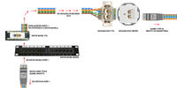
I am posting a small schematic, because I want to understand the principle of operation of ... the whole.
As you can see in the diagram, going from the bottom, I have a SIMPLE patch cord earned in the T568B standard, on the one hand it goes to the Switch, on the other it goes to port 1 to the Patch-panel.
At the back of the patch panel, I sew the cable according to the instructions given on the patch panel ---> then the infrastructure cable goes to the RJ45 socket, which has a DIFFERENT instruction ... as you can see, when connecting according to the instructions from the socket, the wires will be swapped ---> I plug the cable into the socket SIMPLE in T568B standard.

1. Will it work?
2. Shouldn't it be that if I make money in the Patch-Panel (PP) according to the PP instructions, then in the RJ45 socket it should be the same as with PP?
3. I understand the idea of using patch panels as maintaining ergonomics and order in the wardrobe. So why is a patch panel called a patch panel?
4. When connecting a straight cable to the port in the PP - do I have a crossover cable at the output (at the back of the PP)?
I will be grateful for your help.
I am posting a small schematic, because I want to understand the principle of operation of ... the whole.
As you can see in the diagram, going from the bottom, I have a SIMPLE patch cord earned in the T568B standard, on the one hand it goes to the Switch, on the other it goes to port 1 to the Patch-panel.
At the back of the patch panel, I sew the cable according to the instructions given on the patch panel ---> then the infrastructure cable goes to the RJ45 socket, which has a DIFFERENT instruction ... as you can see, when connecting according to the instructions from the socket, the wires will be swapped ---> I plug the cable into the socket SIMPLE in T568B standard.

1. Will it work?
2. Shouldn't it be that if I make money in the Patch-Panel (PP) according to the PP instructions, then in the RJ45 socket it should be the same as with PP?
3. I understand the idea of using patch panels as maintaining ergonomics and order in the wardrobe. So why is a patch panel called a patch panel?
4. When connecting a straight cable to the port in the PP - do I have a crossover cable at the output (at the back of the PP)?
I will be grateful for your help.


