logo elektroda
logo elektroda
X
logo elektroda

Connecting RJ45 Cable to Outlet: Step-by-Step Guide with Socket Reference Image

xmms 60697 19
ADVERTISEMENT
Treść została przetłumaczona polish » english Zobacz oryginalną wersję tematu
  • #1 7138903
    xmms
    Level 11  
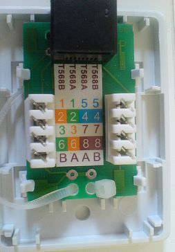
    It is exactly about such a socket
    Connecting RJ45 Cable to Outlet: Step-by-Step Guide with Socket Reference Image

    I always put on the tips and clamped the crimper.
    However, I never connected the cable to the socket. Could I ask for help? Is it also somehow tightening, or is it pushing the cable with a screwdriver into those hooks that are at the angle?
  • ADVERTISEMENT
  • #2 7138938
    bartoshell
    Level 11  
    for "pushing" there are impact knives that cut the cable straight away, but you can use an ordinary, small flat screwdriver. Of course, combine according to the appropriate standard.
  • #3 7138983
    xmms
    Level 11  
    I'm doing a flathead screwdriver. I push in, but I don't know if it comes in. The insulators are to be pulled or normally the cable from each end is squeezed inside and the plates, what are inside, intersect the insulation and touch the copper? This is what it is supposed to look like? Because I don't have a cable tester. But everything is connected according to standard B, you can see on the socket, how to do it, and unfortunately when connecting the patch-cord to the socket and to the computer and on the other end of the cable, the rj45 ends are mounted on the cable also in standard B connected to the router. gets an UNIDENTIFIED NETWORK .. something is not connecting
  • #4 7139061
    yaiba
    Level 22  
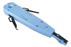
    As for the tool, enter in the Allegro:
    lsa krone knife
    Connecting RJ45 Cable to Outlet: Step-by-Step Guide with Socket Reference Image

    Most likely, you have something wrong.
  • #5 7139074
    bartoshell
    Level 11  
    xmms wrote:
    I'm doing a flathead screwdriver. I push in, but I don't know if it comes in. The insulators are to be pulled or normally the cable from each end is squeezed inside and the plates, what are inside, intersect the insulation and touch the copper? This is what it is supposed to look like? Because I don't have a cable tester. But everything is connected according to standard B, you can see on the socket, how to do it, and unfortunately when connecting the patch-cord to the socket and to the computer and on the other end of the cable, the rj45 ends are mounted on the cable also in standard B connected to the router. gets an UNIDENTIFIED NETWORK .. something is not connecting


    The insulation is to stay on the cable, after pushing it in, it will be cut. Check if the other end of the cable where you want to mount the socket is definitely T568B. Alternatively, plug in 2 pairs of cables (white-orange, orange, white-green, green) and then check the operation
  • #6 7139131
    bestisz
    Level 11  
    Once, when I did not have a Krone tool, I pressed it with the blunt side of a kitchen knife. One for peeling vegetables and potatoes. Do not be afraid to push the cable too much, the deeper it goes, the better, because the contact blades will touch the core more reliably. Of course, we do not remove the insulation from the cables before pressing them in. It happens as you think, i.e. the metal plates in the contact, which are arranged in the shape of the letter "V", cut the insulation and cut into the copper.
    You say that you insert the cables in accordance with the BB markings (in the T568B standard). Also remember that you also need to keep the correct order of the cables in the plug. en standard requires the following order of wires in rj45 plug:

    Sequence from the side of the plug contacts, starting from the left
    1 white pom
    2 orange
    3 white and green
    4 blue
    5 white and blue
    6 green
    7 white-brown
    8 bronze

    If you do not have a LAN meter, maybe you have an ordinary electrician's meter. Set it to measure impedance or resistance and check it after plugging in the cable. Preferably with the help of another person. Let one person touch one of the pins of the meter to the plug's pins and you touch the wires in the socket in the same order (only touch the wires and not the contacts where you insert the individual wires).
    If you do not have a meter, then a 9V battery + bulb + two wires and you will make a classic test tube. You will also check it.

    Good luck.
  • ADVERTISEMENT
  • #7 7140320
    xmms
    Level 11  
    Quote:

    Sequence from the side of the plug contacts, starting from the left
    1 white pom
    2 orange
    3 white and green
    4 blue
    5 white and blue
    6 green
    7 white-brown
    8 bronze


    This is the picture :P
  • #8 7161329
    czaki58
    Level 11  
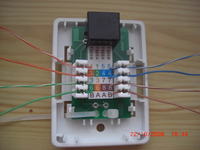
    Hello .... I'm new here and I would like to greet everyone and congratulate on such a nice forum. I was looking for this topic, how to connect these wires, I connected but nothing. And here my question is whether in the attached photo it is correctly done, if not how (maybe someone could to take a photo with the correct connection) thank you in advance and best regards Connecting RJ45 Cable to Outlet: Step-by-Step Guide with Socket Reference Image In the photo this is a trial connection ... so that it is clearly visible if the colors are correctly connected.
  • #9 7161360
    gothye
    Level 33  
    chaki58 Yes, you really did get a nest :)
  • #10 7161450
    czaki58
    Level 11  
    Thanks a lot .... such a photo seemed to me more expressive for me a layman, and maybe it will be useful to others like me, not smart ... greetings :D
  • ADVERTISEMENT
  • #11 12934517
    chieslaw3
    Level 9  
    fresh topic because I do not understand something here

    since standard B is:
    1 white pom
    2 orange
    3 white and green
    4 blue
    5 white and blue
    6 green
    7 white-brown
    8 bronze

    this is why there is a forest in which he placed shaki58
    1 white pom
    2 orange
    3 white and green
    4 green
    5 white-blue
    6 blue
    7 white-brown
    8 bronze

    explain it to me
  • #12 12934532
    edziu
    Level 29  
    Approx
    there are pin numbers on the sticker and what colors should be connected.
  • ADVERTISEMENT
  • #13 12934636
    jimasek
    VIP Meritorious for electroda.pl
    The order is ok, please don't just imitate the stitching. The cable is inserted from the side of the cable tie and the furcation is made as small as possible.
  • #14 14061273
    yakuzja
    Level 13  
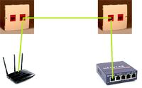
    What if we have a connection between two sockets?

    As in the diagram:

    Connecting RJ45 Cable to Outlet: Step-by-Step Guide with Socket Reference Image

    You need 3 wires, the connection is to be gigabit. Is it not possible to cross between the sockets? Only 1: 1?

    Since I will make a double crossover from one socket, e.g. to a router, will the internal connection between the sockets and the second socket and the switch also be crossed? Is this how I should understand it?
  • #15 14061611
    jprzedworski
    Network and Internet specialist
    yakuzja wrote:
    the connection is to be gigabit
    The 1 Gbit standard has automatic pair detection (it's an option and not obligatory, but it usually works), so you don't need to cross.
  • #16 14062576
    yakuzja
    Level 13  
    Hundred don't need patching too? I thought about connecting the sockets 1: 1, and then how to patch the cables to the socket and that's it. I wrote here about 1000Base-T, but I must admit that I would still have to replace the Router with a faster one, I currently have Fritz! Box 7240 with Neo. However, I am doing a new installation at 1000 Mb / s, because I will buy a switch at 1000 Mb / s. For me, Orange is in no rush with the VDSL2 service; (, 10-20 Mb / s left, but I'm going to use a NAS disk, therefore 1000Mb / s. I just installed the sockets during the renovation, because it is a convenient solution. whether in the plastic tray the LAN cable will not conflict with the SAT-RTV cable (adder), but from what I know it should be ok.
  • #17 14062636
    PiotrPitucha
    Level 34  
    Hello
    We should never cross-connect in sockets, because the sockets are to be universal, the test with the tester itself is cumbersome with cross-sockets.
    It is a good practice to connect all sockets to one standard, I am used to doing it in B, if an old device requires cross-linking, we always do it on a short cable and not on the network between the sockets.
    It is not true that only in 1Gb we have pair detection as it is written about jprzedworski , most new devices detect whether they are connected A or B, for example a quote from the DLink switch instruction:
    Quote:
    All of the ports on the DES-105 support automatic MDI / MDIX crossover, eliminating the need for crossover cables or uplink ports.

    This happens even at 10Mb.
    greetings
  • #18 14062683
    jprzedworski
    Network and Internet specialist
    PiotrPitucha wrote:
    It is not true that only in 1Gb we have pair detection as jprzedworski writes about it
    And where did I write that "only"? However, since it was written that it was 1 Gb, then especially it should work.
  • #19 14128773
    yogishagy
    Level 1  
    Hello,

    by connecting to the topic I will ask for help.

    Description:
    I would like to move the router from point A (living room - RJ45 socket) to point B (hall - box with cables entering the apartment).

    Some time ago there was an IT specialist from Netia and during the internet connection service he connected the router itself to a socket without a modem (originally it was a modem).

    My problem is that after unscrewing the box there is a bunch of network cables (9 wires, 5 of which are loose, not connected and 2 pairs of 2 wires connected (white and gray covers}) with which I can't really find my way.

    Below I will present photos showing the cables entering the apartment.
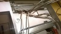
    Connecting RJ45 Cable to Outlet: Step-by-Step Guide with Socket Reference Image
    Here I showed the incoming wires:
    On the right, 5 cables not connected, are marked with numbers / markings: 1,2,5,6,2A
    In the lower right corner - a yellow network cable which will be connected to the router on one side and with magic cabling on the other side (not visible).
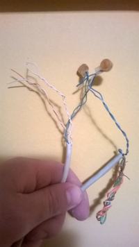
    Connecting RJ45 Cable to Outlet: Step-by-Step Guide with Socket Reference Image
    Here, the wires are marked with 2C and number 3 - I guess this connection is to the telephone line (socket in the hall)
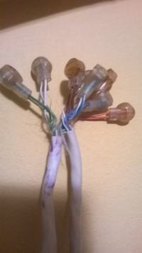
    Connecting RJ45 Cable to Outlet: Step-by-Step Guide with Socket Reference Image
    Another pair labeled 2B and 4

    Being in the electronics store, I was advised to use such an adapter instead of the cuffs visible in the photos - a lower speed drop than on the cufflinks.
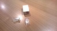
    Connecting RJ45 Cable to Outlet: Step-by-Step Guide with Socket Reference Image


    Going forward, my question is whether it is physically possible to connect the router to these magic wires :) ?
    It is enough to 'connect' to the current one or should a new connection be assembled?

    Thank you for your help,
    If you have any questions, please help.
  • #20 14177713
    yakuzja
    Level 13  
    I changed to the connectors you have in the second and third photos, my attenuation dropped (in the case of ADSL). You can definitely connect to these magic wires. This Netia gives you the LAN immediately and the router has a WAN (without ADSL modem)? Do you have an ADSL Modem? The second photo shows that two wires, i.e. ADSL. The third photo simply shows a "soldered" cable, they taught me that "expensive" mains meters would not show an error, to somehow earn it like plaster sockets or just some connectors of this type. However, fast-connectors are also fine, if you connect on 100m of cable, then maybe it would have to be done precisely, and no one has fun. In the first picture I can see 8 lan cables + power. Where does the cable go from the RJ45 socket? And if you have no idea, mount DLAN adapters and guitar (as long as you have the same phase).

    Or maybe you just have a router that has one WAN / ADSL socket and you still have ADSL only an RJ45 socket. That's what I have in Fritz! Box 7240

Topic summary

The discussion revolves around connecting an RJ45 cable to a socket, specifically addressing the correct method for inserting the cable into the socket's contacts. Users share various techniques, including using a flathead screwdriver or a Krone tool to push the cable into the socket, ensuring that the insulation remains intact while the metal contacts cut through to make a connection. The importance of adhering to the T568B wiring standard is emphasized, with detailed pin configurations provided. Users also discuss troubleshooting connectivity issues, such as receiving an "UNIDENTIFIED NETWORK" error, and the necessity of verifying that both ends of the cable are wired according to the same standard. Additional queries about cross-connecting sockets and the implications for gigabit connections are also addressed, highlighting that modern standards often allow for automatic pair detection.
Summary generated by the language model.
ADVERTISEMENT