logo elektroda
logo elektroda
X
logo elektroda

Arduino - Generating PWM signal at a given frequency, independent

DarkMajster 7533 7
ADVERTISEMENT
Treść została przetłumaczona polish » english Zobacz oryginalną wersję tematu
  • #1 16177607
    DarkMajster
    Level 11  
    I need to generate a PWM signal with high frequency and 50% filling on any pin
    However, when I do something like that


    Code: C / C++
    Log in, to see the code


    It's ok until you enter further code and delays needed to implement them ...
    When I leave such a delay to the whole, it is so small that various things go crazy, e.g. the display writes so fast that I can't see it with the human eye, whether it is possible to do something in the style of void loop2, which will repeat regardless of the void loop ?
    I will add that I have arduino mega 2560
  • ADVERTISEMENT
  • #2 16177756
    lagrange
    Level 9  
    The analogWrite (x) function allows you to set PWM on pins. In Mega it works on pins 2 - 13 and 44 - 46. The argument defines the degree of PWM filling, for 50% it will be 127.

    This way you can eliminate the need for loops to get PWM.

    https://www.arduino.cc/en/Reference/analogWrite
  • ADVERTISEMENT
  • #3 16177780
    andrzej55
    Level 37  
    DarkMajster wrote:
    I need to generate a high frequency PWM signal on any pin

    Ie. what exactly? As standard, Arduino on PWM outputs generates about 400 Hz.
  • #4 16177787
    gdkj
    Level 26  
    The first shot that comes to mind is a new variable, added from scratch by one every cycle in the main loop, it can be compared to the number at which the variable resets and changes the state of any pin to the opposite. The higher the number at which the variable (the sum increased by one step) resets and changes the state of the selected pin, the lower the signal frequency.
    If there are any additional loops in the main loop, of course, they disrupt the symmetry of filling and frequency, and for this separate processors were invented in the processors
    to which you put only settings and data but they count after the program.
    Regards.
  • ADVERTISEMENT
  • ADVERTISEMENT
  • #6 16177836
    DarkMajster
    Level 11  
    lagrange wrote:
    The analogWrite (x) function allows you to set PWM on pins. In Mega it works on pins 2 - 13 and 44 - 46. The argument defines the degree of PWM filling, for 50% it will be 127.

    This way you can eliminate the need for loops to get PWM.

    https://www.arduino.cc/en/Reference/analogWrite


    What about frequency?
  • #7 16177878
    lagrange
    Level 9  
    DarkMajster wrote:

    What about frequency?


    "The PWM default frequency is 490 Hz for all pins, with the exception of pin 13 and 4, whose frequency is 980 Hz"

    The ATMega 2560 microcontroller in Arduino works at 16MHz as far as I remember, but it is worth remembering that every digitalWrite needs a few instructions back and forth. Adding to this the remaining program code, it is unlikely to achieve a better result than on pins 13 and 4.

    Although, of course, the answer to the question about the value of the frequency you require is crucial throughout the discussion.
  • #8 16177934
    DarkMajster
    Level 11  
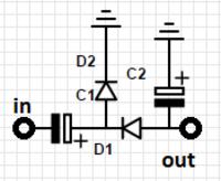
    Well, I found the LCD display PHICO D-0 172-H1-0C, connected it, there was a problem with contrast, when I gave him weight for the control pin it, it was the best, the inscription was gently visible, I came to the conclusion that I had to give him voltage negative, so I figured out that I would do the layout as in the diagram
    Arduino - Generating PWM signal at a given frequency, independent
    I gave 2 2.2 micro capacitors I typed in arduino what at the beginning of the topic, I gave the code to display in void setup (after entering the loop nothing was displayed due to the very high frequency of the loop) I gave out to the pin from the contrast and it worked as it should.
    The problem is of course when I want to use the display for something other than writing good morning on it :D

    Added after 10 [minutes]:

    Well, I just connected this circuit under PWM at 50% filling and 1kHz and I was able to get what I wanted, thank you very much for your help

Topic summary

The discussion revolves around generating a high-frequency PWM signal with a 50% duty cycle on an Arduino Mega 2560. The user initially attempted to use digitalWrite and delay functions, which led to issues with timing and display visibility. Responses suggested using the analogWrite function for PWM generation, which simplifies the process by allowing direct control of PWM duty cycles. The TimerOne library was recommended for more precise frequency control. The default PWM frequency for most pins is 490 Hz, with exceptions for pins 13 and 4 at 980 Hz. The user successfully implemented a 1 kHz PWM signal after addressing display contrast issues related to high-frequency updates.
Summary generated by the language model.
ADVERTISEMENT