logo elektroda
logo elektroda
X
logo elektroda

Arduino R4 - DAC tutorial, i.e. we generate a sine wave and play a melody

p.kaczmarek2 3201 4
ADVERTISEMENT
Treść została przetłumaczona polish » english Zobacz oryginalną wersję tematu
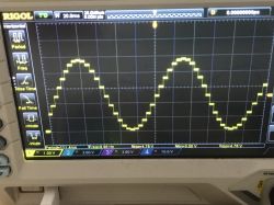
  • Arduino R4 generating a sine wave signal on a Rigol DS1054Z oscilloscope
    Arduino R4 has a built-in 12-bit DAC (Digital-to-Analog Converter), which means it is able to generate an analog signal without connecting additional modules. This is a big step forward, because in the case of the older Uno R3 and similar boards we had to connect an external DAC such as the MCP4725 and control them usually via SPI or I2C to obtain a sine wave. And here you can generate it directly from pin A0. In this topic, I will briefly show how to run a DAC on Arduino R4 and take a look at the generated signal on an oscilloscope.

    DAC - sine wave on Arduino R4
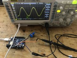
    Let's consider an example from the Arduino documentation. This example reads the voltage value from the potentiometer and converts it to the frequency of the generated sine wave on the DAC. The potentiometer serves as a voltage divider, the extreme pins on VDD and GND, and the middle pins on the ADC. Below is its corrected code, because at the time of writing the topic there was an error in the Arduino documentation, the wrong pin was used once - A0 instead of A5.
    Code: C / C++
    Log in, to see the code

    The potentiometer is connected to A5, and there is a DAC output to A0.
    The map function, as the name suggests, maps the read value from the ADC, which is in the range from 0 to 1024 (10-bit ADC), to the frequency, the range of which we have chosen is from 0 to 10kHz.
    Here is the result:
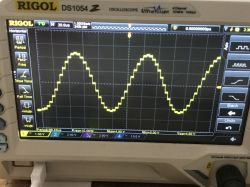
    Oscillogram displaying a sine wave signal generated by Arduino R4 on an oscilloscope screen.
    Oscilloscope display showing a sine wave generated by Arduino R4
    The oscillograms show very nicely how the DAC creates an approximation of a sine wave sufficient for many applications. If we want to generate another function, we also have the following options:
    Code: C / C++
    Log in, to see the code

    or
    Code: C / C++
    Log in, to see the code

    DAC from Arduino can be used, for example, to generate melodies, here is the code from the official documentation:
    Code: C / C++
    Log in, to see the code

    The above code generates the melody "Frere Jacques", plays a sequence of notes and rhythms, using the AnalogWave library to generate sound waves. The melody is played on the speaker using a DAC and audio amplifier (LM386), and parameters such as pitch, melody, rhythm, tempo and note length are defined in the code.

    The full specification of Arduino R4 (in its available versions) can be found on the Arduino website:
    https://docs.arduino.cc/hardware/uno-r4-wifi
    https://docs.arduino.cc/resources/datasheets/ABX00087-datasheet.pdf

    Summary
    It's hard to disagree that the typical beginner will have a lot to run and play with with the Arduino R4. There is much more on board this board than in the iconic R3, it even offers the DAC discussed here, which allows you to generate a sine wave without connecting external modules. Just a few contact cables are enough.
    Still, I wonder how often these DACs might come in handy? Have you used DACs in your projects and if so, which ones? Or maybe in R4 it is just an unnecessary gadget? I invite you to discuss.

    Cool? Ranking DIY
    Helpful post? Buy me a coffee.
    Do you have a problem with Arduino? Ask question. Visit our forum Arduino.
    About Author
    p.kaczmarek2
    Moderator Smart Home
    Offline 
    p.kaczmarek2 wrote 11922 posts with rating 9984, helped 572 times. Been with us since 2014 year.
  • ADVERTISEMENT
  • #2 20808841
    tmf
    VIP Meritorious for electroda.pl
    Sometimes a DAC is useful, but when playing music the same can be done using PWM + low-pass filter. So there is no great advantage of DAC here IMHO.
    Since this processor has DMA, it would be more interesting to connect the board with the DAC via DMA. Besides, IMHO, a DAC mainly makes sense if the processor allows, for example, programmatic switching of the output, e.g. to the input of the built-in comparator, ADC, etc.
    However, I still don't understand why such a board is needed - it has two processors on board - the second one is on the ESP32 module, what is the point of packing a relatively slow processor if we have ESP32 on board? To complicate the software? :)
  • ADVERTISEMENT
  • #3 20809560
    Janusz_kk
    Level 39  
    tmf wrote:
    what's the point of packing a relatively slow processor if we have ESP32 on board?

    Because it has more legs and runs on 5V?
  • ADVERTISEMENT
  • #4 20812810
    tmf
    VIP Meritorious for electroda.pl
    Janusz_kk wrote:
    Because it has more legs and runs on 5V?

    Probably not, because if I count correctly, there are approximately 22 IO pins (Arduino) + approximately 10 additional pins on this board. A total of approximately 32 IO pins, and the ESP32 has 34 IO pins.
    5V is an advantage, but it's also rather average at the moment... It's more about promoting the product. Only it turned out to be the same nonsense as in the case of RPi pico W - a separate MCU and a separate radio module - if someone needs a radio, they buy ESP and there is no need to complicate their life...
  • #5 20812833
    khoam
    Level 42  
    tmf wrote:
    ESP32 has 34 IO pins.

    This board has ESP32-S3, which has 45 GPIOs.
ADVERTISEMENT