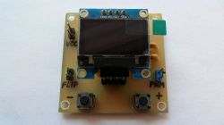
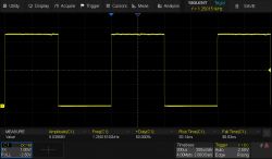
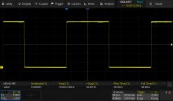
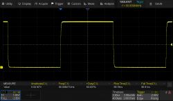
A simple PWM (Pulse-Width Modulation) generator built on an ATtiny24/44/84 microcontroller, supplied with stabilised voltage Vcc=2.7-5.5V (2.4-5.5V if using the "A"/"V" version of the microcontroller). Its output produces a rectangular signal with a selected fixed frequency of 1.25/10/80 kHz and a filling adjustable in the range 0-100%, in 1% steps. The parameters of the output signal are presented on a monochrome OLED display (SSD1306 controller, I2C bus), with a resolution of 128x32/128x64 pixels and address $78 ($3C)/$7A ($3D). I wrote the control program in assembler and it is identical for each of the microcontrollers mentioned.
I recently wrote my own routines in assembler to handle the I2C bus and the OLED display . I was looking for a way to use them in some practical device and so the idea of making this generator came about. I used an ATtiny44 microcontroller in an SO14 enclosure, because I happen to have a lot of them from disassembly. It is the second version of the simple PWM generator I made a few years ago .
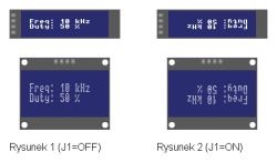
When switched on, a rectangular signal with a frequency of 10 kHz, a filling of 50% and a level dependent on the value of the supply voltage Vcc is obtained at the generator output (connector CON2) (Figure 1). If jumper J1 (FLIP) is short-circuited (ON) during power-up, the displayed image will be rotated 180 degrees (Figure 2). If the OLED display is not detected after power-up, the generator will operate normally without it. A 128x64 display is treated as 128x32, so the image displayed on it has 1-line horizontal gaps (every second horizontal line is blank, causing the image to be stretched vertically).
To reduce/increase the signal fill by 1%, press the S1 (DUTY-)/S2 (DUTY+) button (microstick) briefly (less than 250ms). Pressing and holding down the S1/S2 button for a longer period of time will continuously decrease/increase the fill value at a rate of approx. 4%/s, until the limit value is reached, i.e. 0%/100% respectively. A fill setting of 0%/100%, will force a continuous low/high logic state (GND/Vcc) at the generator output.
To change the frequency of the signal, briefly (less than 1s) press both buttons S1 and S2 simultaneously. The frequency will then change to the next value in the sequence: 10/80/1.25 kHz and so on over and over again. Pressing and holding the S1 and S2 buttons at the same time for a long time will continuously change the frequency value at a rate of approx. 1x/sec until the buttons are released. After each frequency change, the initial signal fill value is always 50% (regardless of the previous setting).
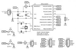
The quartz resonator X1 clocks the microcontroller so that the output signal is fairly accurate/stable in frequency and the time waveforms of the OSCL/OSDA signals are precise/symmetrical with respect to each other. It is also possible to clock the microcontroller with its internal RC oscillator, with a nominal frequency of 8 MHz. The advantage of this solution is that it is then not necessary to mount a resonator X1 and capacitors C3/C4, but a major disadvantage is the very inaccurate/unstable frequency of the output signal and the degraded quality of the time waveforms of the OSCL/OSDA signals. Capacitors C1 and C2 filter the supply voltage. Resistor R2 limits the current drawn directly from the microcontroller's PA7 pin - preventing it from being damaged if the CON2 output is shorted.
When programming, remember to set the fuse/lock bits appropriately:
1. when the microcontroller will be clocked with the X1 quartz resonator:
FL (Fuse Low): $FF, FH (Fuse High): $DF, FE (Fuse Extended): $FF, LB (Lock Bits): $FF.
2. when the microcontroller is clocked by the internal RC oscillator:
FL (Fuse Low): $E2, FH (Fuse High): $DF, FE (Fuse Extended): $FF, LB (Lock Bits): $FF.
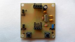
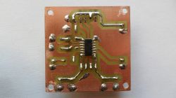
The generator can be supplied with DC voltage Vcc=2.7(2.4)-5.5V from a power supply or from batteries/batteries (e.g. one 18650 type cell). It is not protected in any way against reverse connection of the supply voltage Vcc. Mistaking the polarity of this voltage will damage the microcontroller. Current consumption without OLED display at Vcc=2.7/5V, is a maximum of 2.5/6.5mA (80kHz/99% signal, generator output not loaded). The current consumption with the 128x64 pixel OLED display at Vcc=5V, is 8mA maximum. I assembled the generator on a 45x45mm single-sided board, made by chemical transfer. The board is designed to use a 38x12mm (128x32) or 28x28mm (128x64) display, which has the signals arranged in order: GND, VCC, SCL, SDA. The pull-up resistors for the OSCL/OSDA lines for the OLED were not placed on the generator board, as the display module board contains them. The minimum supply voltage needed to operate the OLED display, is approximately Vcc=1.8V (low brightness).
 .
.
The attached archive contains: schematic in Eagle, board in DipTrace, source, batch and documentation in PDF. Project page: Link .
.
I recently wrote my own routines in assembler to handle the I2C bus and the OLED display . I was looking for a way to use them in some practical device and so the idea of making this generator came about. I used an ATtiny44 microcontroller in an SO14 enclosure, because I happen to have a lot of them from disassembly. It is the second version of the simple PWM generator I made a few years ago .
When switched on, a rectangular signal with a frequency of 10 kHz, a filling of 50% and a level dependent on the value of the supply voltage Vcc is obtained at the generator output (connector CON2) (Figure 1). If jumper J1 (FLIP) is short-circuited (ON) during power-up, the displayed image will be rotated 180 degrees (Figure 2). If the OLED display is not detected after power-up, the generator will operate normally without it. A 128x64 display is treated as 128x32, so the image displayed on it has 1-line horizontal gaps (every second horizontal line is blank, causing the image to be stretched vertically).
To reduce/increase the signal fill by 1%, press the S1 (DUTY-)/S2 (DUTY+) button (microstick) briefly (less than 250ms). Pressing and holding down the S1/S2 button for a longer period of time will continuously decrease/increase the fill value at a rate of approx. 4%/s, until the limit value is reached, i.e. 0%/100% respectively. A fill setting of 0%/100%, will force a continuous low/high logic state (GND/Vcc) at the generator output.
To change the frequency of the signal, briefly (less than 1s) press both buttons S1 and S2 simultaneously. The frequency will then change to the next value in the sequence: 10/80/1.25 kHz and so on over and over again. Pressing and holding the S1 and S2 buttons at the same time for a long time will continuously change the frequency value at a rate of approx. 1x/sec until the buttons are released. After each frequency change, the initial signal fill value is always 50% (regardless of the previous setting).
The quartz resonator X1 clocks the microcontroller so that the output signal is fairly accurate/stable in frequency and the time waveforms of the OSCL/OSDA signals are precise/symmetrical with respect to each other. It is also possible to clock the microcontroller with its internal RC oscillator, with a nominal frequency of 8 MHz. The advantage of this solution is that it is then not necessary to mount a resonator X1 and capacitors C3/C4, but a major disadvantage is the very inaccurate/unstable frequency of the output signal and the degraded quality of the time waveforms of the OSCL/OSDA signals. Capacitors C1 and C2 filter the supply voltage. Resistor R2 limits the current drawn directly from the microcontroller's PA7 pin - preventing it from being damaged if the CON2 output is shorted.
When programming, remember to set the fuse/lock bits appropriately:
1. when the microcontroller will be clocked with the X1 quartz resonator:
FL (Fuse Low): $FF, FH (Fuse High): $DF, FE (Fuse Extended): $FF, LB (Lock Bits): $FF.
2. when the microcontroller is clocked by the internal RC oscillator:
FL (Fuse Low): $E2, FH (Fuse High): $DF, FE (Fuse Extended): $FF, LB (Lock Bits): $FF.
The generator can be supplied with DC voltage Vcc=2.7(2.4)-5.5V from a power supply or from batteries/batteries (e.g. one 18650 type cell). It is not protected in any way against reverse connection of the supply voltage Vcc. Mistaking the polarity of this voltage will damage the microcontroller. Current consumption without OLED display at Vcc=2.7/5V, is a maximum of 2.5/6.5mA (80kHz/99% signal, generator output not loaded). The current consumption with the 128x64 pixel OLED display at Vcc=5V, is 8mA maximum. I assembled the generator on a 45x45mm single-sided board, made by chemical transfer. The board is designed to use a 38x12mm (128x32) or 28x28mm (128x64) display, which has the signals arranged in order: GND, VCC, SCL, SDA. The pull-up resistors for the OSCL/OSDA lines for the OLED were not placed on the generator board, as the display module board contains them. The minimum supply voltage needed to operate the OLED display, is approximately Vcc=1.8V (low brightness).


 .
.
The attached archive contains: schematic in Eagle, board in DipTrace, source, batch and documentation in PDF. Project page: Link .
.
Cool? Ranking DIY Helpful post? Buy me a coffee.


