logo elektroda
logo elektroda
X
logo elektroda

[Solved] - Cartridge Black Box v8 Diagram / Element List for Commodore 64: Seeking Assembly Info

MES Mariusz 6252 15
ADVERTISEMENT
Treść została przetłumaczona polish » english Zobacz oryginalną wersję tematu
  • #1 16186106
    MES Mariusz
    Level 36  
    Hey.

    Does anyone have references to the diagram / list of elements for the Black Box v8 cartridge for Commodore 64?
    I am asking because I have a PCB (I want to assemble it), but I don't know what components are sitting on it. Thanks in advance.
  • ADVERTISEMENT
  • Helpful post
    #2 16186804
    MCbx
    Level 28  
    In my version: 74LS175, 4001 NOR (or 74LS08 AND), 27C256.
    Description of how switching works: http://oldcomputer.info/8bit/apcartridges/reprod/index.htm " target="_blank" rel="nofollow noopener ugc" class="postlink inline" title="" > http://oldcomputer.info/8bit/apcartridges/reprod/index.htm .
    My guess is there were clones with slightly different composition but similar switching mechanisms. I managed to assemble it. As far as I remember:
    - EPROM lines A0..A13 to the corresponding cartridge connector, same with the data.
    - A14 controlled by / Q2 of 74LS175 chip
    - 74LS175 data inputs connected to A0, A1, A2.
    - Q0 -> / EXROM, Q1 -> / GAME, / Q2 -> A14, / Q3 -> EPROM pin 1. That's in case of expansion to 27512.
    - 74LS175 CLK to IO2
    - RESET cartridge also resets 74175
    This way you can "click" any state system into the system only by selecting the address.
    CD4001 - 3 gates linked in "AND" controls / OE EPROM from ROML and ROMH.
    It's out of memory, so check it out again.
  • ADVERTISEMENT
  • #3 16187782
    MES Mariusz
    Level 36  
    Thank you very much.

    Because the data is not complete everywhere (diagrams, gerberas, batch are not everywhere), I will be grateful for adding data in the subject that will allow you to recreate various Commodore 64 cartridges.

    Once, I even managed to find a set of Gerberas for Final III on the Internet - today I can't dig it out - it seems that the site has disappeared from the server.

    best regards
    Mariusz
  • Helpful post
    #4 16188617
    LA72
    Level 41  
    MES Mariusz wrote:
    Once, I even managed to find a set of Gerberas for Final III on the Internet - today I can't dig it out - it seems that the site has disappeared from the server.

    best regards
    Mariusz


    Here there are some projects including FC III.
  • #5 16189557
    MES Mariusz
    Level 36  
    MCbx wrote:
    In my version: 74LS175, 4001 NOR (or 74LS08 AND), 27C256.
    Description of how switching works: http://oldcomputer.info/8bit/apcartridges/reprod/index.htm " target="_blank" rel="nofollow noopener ugc" class="postlink inline" title="" > http://oldcomputer.info/8bit/apcartridges/reprod/index.htm .
    My guess is there were clones with slightly different composition but similar switching mechanisms. I managed to assemble it. As far as I remember:
    - EPROM lines A0..A13 to the corresponding cartridge connector, same with the data.
    - A14 controlled by / Q2 of 74LS175 chip
    - 74LS175 data inputs connected to A0, A1, A2.
    - Q0 -> / EXROM, Q1 -> / GAME, / Q2 -> A14, / Q3 -> EPROM pin 1. That's in case of expansion to 27512.
    - 74LS175 CLK to IO2
    - RESET cartridge also resets 74175
    This way you can "click" any state system into the system only by selecting the address.
    CD4001 - 3 gates linked in "AND" controls / OE EPROM from ROML and ROMH.
    It's out of memory, so check it out again.


    Thank you for valuable information.

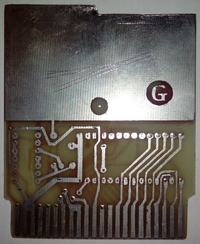
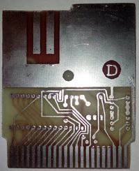
    My PCB looks like below. Immediately I will give you what I should cover.


    - Cartridge Black Box v8 Diagram / Element List for Commodore 64: Seeking Assembly Info

    - Cartridge Black Box v8 Diagram / Element List for Commodore 64: Seeking Assembly Info

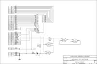
    I wonder if it won't be just this:

    - Cartridge Black Box v8 Diagram / Element List for Commodore 64: Seeking Assembly Info

    It is true that this is for the Black Box version III.

    The ROM for v8 is supposedly on 27c256 (28 pin), at least this is what the package shows:
    http://csdb.dk/release/download.php?id=105832

    This would match the EPROM space (28 pin) on my PCB.
  • Helpful post
    #6 16190120
    MCbx
    Level 28  
    It really doesn't want to be BBv8. Switching banks in BBv3, v4 and v8 was completely different.
    I'm writing this late so please check back. I haven't made "cartridges" for a long time.

    EPROM has address lines connected directly, that is probably up to max. 27128, 27128 had Black Box v4. Pin 27 (in 27256 is A14) ends with a pad that I do not know where it should be connected.
    Note that from unknown logic it goes to pin 22 (/ OE) EPROM line - this looks like a memory activator from BBv4. So suppose / OE = / ROMH AND / ROML. That's how it used to be in BBv4.
    / OE is generated from a gate whose two inputs are connected to each other and the output of another (3 pins connected). Assuming that it is NAND, we have an inverter connected to the output of the NAND gate.
    So let's note that one of the inputs of the previous NAND is connected to pin B, i.e. / ROMH, and the other is wandering around EPROM to pin 11, or / ROML. That's exactly the BBv4 deal.

    The other gates must be used to control GAME / EXROM. Feathers 8 and 9 are / GAME and / EXROM connected together go through a grommet to the gate pin 6 output and the input - pin 2. Pin 3 connects to 4 which looks like a flip-flop. I suspect that the inputs are IO2 and IO1 through resistors, as in the diagram from Mr. Sobola.

    Ergo:
    1. It's not BBv8, probably BBv4 ( screenshot here ).
    2. The digital circuit is 74LS00 or a similar variation 74xx00.

    best regards

    PS
    If someone wants to learn more about all this banking, I recommend reading issue 6 of C&A Fan magazine. There was even an interview with Mr. Romuald Drahokaupil, the creator of Black Box, and drawings of typical cartridge mechanisms.
  • #7 16190182
    MES Mariusz
    Level 36  
    It is strange that I am almost sure that there were Bb v8 mounted on this PCB. Unless it was some non-original / modified batch, it certainly was a synthesis of Polish speech, joystick tests, etc.

    MCbx wrote:
    If someone wants to learn more about all this banking, I recommend reading issue 6 of C&A Fan magazine. There was even an interview with Mr. Romuald Drahokaupil, the creator of Black Box, and drawings of typical cartridge mechanisms.


    It seems that the website http://www.ca-fan.pl/ no longer exists. and, out of spite, I can't find number 6: - /
  • Helpful post
    #8 16191111
    MCbx
    Level 28  
    If it was BBv8, it would have to be some modified and optimized batch. I am sure of this BBv4, because I made such a clone and used exactly this chip on the 74LS00.

    The ca-fan site doesn't exist, but what they are for Online fillets ?.
  • ADVERTISEMENT
  • ADVERTISEMENT
  • #10 16191330
    MES Mariusz
    Level 36  
    wejog wrote:
    I have no. 6 from 2010, below the whole, a bit mare, but it is


    A colleague gave the links above. But points for trouble :-)


    --- edit ---

    Hello after a few days.

    I have read "We Build Cards" on pages 84-85 " Commodore and Amiga fan "and I have a slight problem understanding a certain point, which is what I underlined in red:

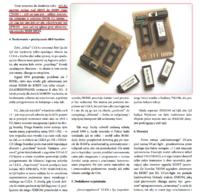
    - Cartridge Black Box v8 Diagram / Element List for Commodore 64: Seeking Assembly Info

    - Cartridge Black Box v8 Diagram / Element List for Commodore 64: Seeking Assembly Info

    If I understand correctly then:

    The counter program reads $ FFFC, finds a redirection to $ FCE2, here to $ 8005 and reads subsequent characters, up to $ 8009, these characters should create the string "CBM80", but whether this string is there anyway, it doesn't matter. because it will be redirected to the address $ 8000 anyway and the reading starts loading subsequent characters into the memory up to the address $ 9FFF.

    Sounds slightly absurd. Anyway, from $ 8005 to $ 8009 there is going to be the string CBM80 and then backwards and again from $ 8000, where again from $ 8005 will be the string CBM80 again?

    The article seems to be written from scratch (for everyone) and after a while we enter the level of abstraction on average understandable to anyone.


    Another thing that seems to be discussed in detail, and not necessarily clear / transparent / understandable, is bank switching:
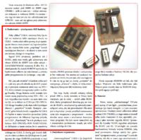
    - Cartridge Black Box v8 Diagram / Element List for Commodore 64: Seeking Assembly Info

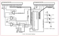
    As I understand it, C64 has a 13 bit address bus (A0 ... A12). At least this is what I conclude by looking at the diagram:
    - Cartridge Black Box v8 Diagram / Element List for Commodore 64: Seeking Assembly Info

    To address larger EPROM memories, you need to issue another three address signals (A13, A14 and A15). It is done, as I can see, by controlling the 74LS90 counter with the FI2 signal (I have to read what it is and what it does, because the article shows it on average).

    Oh and okay, a honey miracle. But whether the point is that when the data from the first 8 kB "bank" is loaded, the bank will switch from the machine (another combination will be set on shafts A13 ... A15). What event in the system causes the FI2 signal? Or maybe the behavior of this signal is somehow programmatically defined at the beginning of the program from the EPROM batch? Some kind of bootloader in the initial section?

    8192 bytes can be addressed with 13 bits (A0 ... A12). After addressing these 8192 bytes, does the counter "realize" that so many have been counted and issue the line A13, after counting 8128 bytes, it sets A14 and turns off A13, after counting another 8192 bytes it turns on A13 again and so on?

    I will be very grateful if someone enlightens me.

    Thank you very much.
    Mariusz
  • #11 16201369
    MCbx
    Level 28  
    As far as I remember, the CBM80 string is used to find the correct connected ROM in the car. There is no CBM80, so there is no ROM jump. Anyway, this string comes from cart memory so it is read and you can use signals existing at cart read. See https://www.c64-wiki.com/index.php/Cartridge#Cartridge_boot-up " target="_blank" rel="nofollow noopener ugc" class="postlink inline" title="" > https://www.c64-wiki.com/index.php/Cartridge#Cartridge_boot-up
    If the ROM is attached to memory somewhere (the / GAME, / EXROM lines), but the CBM80 string is not there, the kernal continues booting as if the ROM was not there, leaving its possible access for later, e.g. user software.

    You just found UCart ... As part of learning assembler, I made modifications to make it a menu.
    At the beginning I give the original Sysop, i.e. the UCart operating program, somehow these topics from the C64 forum have disappeared (maybe two well-known rival gentlemen who are passionate about C64 are already making commercial clones of it? ;) ), and I will refer to it when translating:
    [code:1:5ac760d923]
    *= $8000
    BYTE COLD
    BYTE COLD
    BYTE $C3,$C2,$CD,$38,$30

    COLD
    SEI
    CLD
    LDX #$FF
    TXS
    LDA #$37
    STA $01

    STX $D016
    JSR $FDA3
    LDA #$00
    TAX
    TAY

    LP1
    STA $02,Y
    STA $0200,Y
    STA $0300,Y
    INY
    BNE LP1
    LDY #$A0

    STY $C2
    STA $C1

    JSR $FE2D
    JSR $FD90
    JSR $FD15
    JSR $FF5B
    JSR $E453
    JSR $E3BF
    JSR $A644
    SEI
    LDX #$FB
    TXS

    LDA #DANE
    STA $FC

    LDA #$01
    STA $FD
    LDA #$08
    STA $FE
    LDY #$00
    L2
    LDA ($FB),Y ;1SZE 8KB
    STA ($FD),Y
    INY
    BNE L2

    INC $D020
    INC $FC
    INC $FE
    LDA $FC
    CMP #$A0
    BCC L2
    LDA $FD
    SEC
    SBC #
  • #12 16202026
    MES Mariusz
    Level 36  
    Thanks for the next hints. I process and assimilate.

    However, I am curious if there is any simple method to process the batch, e.g .:

    http://c64power.com/forum/uploads/files/BB8.zip

    to the form of assembler code as above (disassembly of machine code - that's what it's professionally called)

    Are there any C64 or PC tools for this?
  • #13 16202112
    MCbx
    Level 28  
    There is, but the problem is that it often processes "as is" without discriminating data from program, so it requires even more work to reverse engineer separating each other. Such a disassembler would convert even this "CBM80" into commands. But I debugged the Sysop code using a debugger integrated with some emulator (probably VICE), it showed what was happening and made it possible to work step by step. Theoretically, this would make it possible to recreate the code, in practice it is very laborious, because you know what is happening, but you need to know why.

    To write assembler and generate from it I used CBMPrgStudio (http://www.ajordison.co.uk/ " target="_blank" rel="nofollow noopener ugc" class="postlink inline" title="" > http://www.ajordison.co.uk/ ), this is a combine and it also has a debugger. But on CSDB (http://csdb.dk/ " target="_blank" rel="nofollow noopener ugc" class="postlink inline" title="" > http://csdb.dk/ ) there are a lot of tools for C64, both for Commodore and other platforms.
  • #14 16676393
    MES Mariusz
    Level 36  
    MCbx wrote:
    It really doesn't want to be BBv8. Switching banks in BBv3, v4 and v8 was completely different.

    Hello.

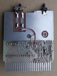
    I found a moment and realized that it had to be a BlackBox (maybe v8), the operating mode of which was switched with a slide switch.

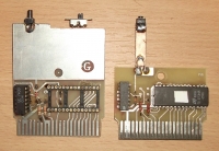
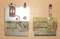
    Below are photos of the original Black Box (on the right) and the pre-assembled PCB of the Black Box, for which I have the input described as v8.

    - Cartridge Black Box v8 Diagram / Element List for Commodore 64: Seeking Assembly Info

    - Cartridge Black Box v8 Diagram / Element List for Commodore 64: Seeking Assembly Info

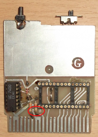
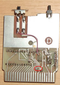
    I assume that the connection of the slide switch is like in the photo (plus or nothing), but it could be connected differently (plus or minus to the EPROM address).

    There is one more place I am not sure what to connect to:

    - Cartridge Black Box v8 Diagram / Element List for Commodore 64: Seeking Assembly Info - Cartridge Black Box v8 Diagram / Element List for Commodore 64: Seeking Assembly Info

    Except that I can see that the original (on the left) also has nothing in this place. So it looks like these are just vias.

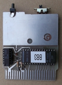
    Okay, I put a PCB Black Box III on it using the batch z this page .

    - Cartridge Black Box v8 Diagram / Element List for Commodore 64: Seeking Assembly Info

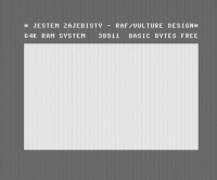
    I put it in C64 and I see that someone was "zaje ..." ;-)

    - Cartridge Black Box v8 Diagram / Element List for Commodore 64: Seeking Assembly Info

    It's nice that he was busy ... but why don't I know the flashing cursor? In other words, the cart is supposed to load, but the C64 seems to be frozen because the blinking cursor is missing.

    I would like to rule out blame for the charge. Will someone send me your BB V3 or V4 batch? Please share your dunks for (any) cards. Thank you :-) - Cartridge Black Box v8 Diagram / Element List for Commodore 64: Seeking Assembly Info
  • #15 17327828
    11111olo
    Level 42  
    Mariusz, your knowledge is so miserable that it is surprising that you did something.
    The operation of all this is done in the most primitive way - it can't be more "rude".

    Moderated By gulson:

    3.1.9. Do not be ironic and do not be malicious towards the other side of the discussion. Please respect dissenting opinion and other opinions in the forum.

  • #16 17327958
    MES Mariusz
    Level 36  
    Thank you for your honesty, and what a generous contribution in the form of "how simple" and "you're weak" ;-)
    We treat complexes? ;-)

    I see that you like to dig up old posts, and against the background of supposedly weaker posts, shine your supposedly wide and so forward knowledge (in the form of "I know and you don't know, hehehehehe" ;-) Bravo! ;-p

    But let's do something useful for the forum, let's write how the problem was resolved, and close the topic.

    Well, the lack of the cursor was caused by a badly programmed EPROM (or more precisely the technical problems of the programmer).
    After eliminating the problems of the programmer, the batches load nicely, and on C64 the BBv3 batches start correctly on these PCBs (and from what I remember, BBv4 could also be run on these PCBs after very slight modifications).

    I also greet my friend who is shining with a comprehensive and very powerful knowledge, and I close the topic ;-) .

    PS. Next time, share your knowledge, enlighten someone on the topic on which he is stuck, instead of boasting about supposed knowledge, like a big limousine, hiding the body, slightly smaller in size ;-)

    Good luck in shining for strength and for show. "Hold on" healthy :-)

    Added after 45 [seconds]:

    Technical issues with the EPROM programmer have been eliminated.

Topic summary

Discussion revolves around the assembly of the Black Box v8 cartridge for the Commodore 64, with users seeking and sharing information on the necessary components and diagrams. Key components mentioned include 74LS175, 4001 NOR, and 27C256 EPROM. Users discuss the differences in switching mechanisms between various Black Box versions and share links to resources for further information. The conversation also touches on the challenges of disassembling and understanding the cartridge's operation, with references to tools like CBMPrgStudio for programming and debugging. The final resolution indicates that issues with the cursor were due to programming errors in the EPROM, which were subsequently corrected.
Summary generated by the language model.
ADVERTISEMENT