logo elektroda
logo elektroda
X
logo elektroda

Using NPN Transistor for PIC-Controlled ON-OFF Switch with VMusic3, Bluetooth, or DAB+ Radio

silelis 5112 8
ADVERTISEMENT
Treść została przetłumaczona polish » english Zobacz oryginalną wersję tematu
  • #1 16353186
    silelis
    Level 12  
    Hi,

    I design a PIC-controlled system and I want the transistor to be a kind of relay that turns the power on to equal electronic modules (e.g. VMusic3, Bluetooth, or DAB + MonkeyBoard radio) that are the periphery of the system (controlled by PIC).

    In most cases, I encounter this kind of NPN transistor application:
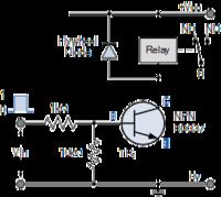
    Using NPN Transistor for PIC-Controlled ON-OFF Switch with VMusic3, Bluetooth, or DAB+ Radio

    However, in my case, it would be easier for me if I connected it like this:
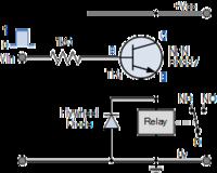
    Using NPN Transistor for PIC-Controlled ON-OFF Switch with VMusic3, Bluetooth, or DAB+ Radio

    Will the NPN transistor connection shown in the 2nd picture work and will I have something like an ON-OFF button controlled by the microcontroller output?

    So far I have made a circuit consisting of an NPN and PNP transistor (as below), but I need a bit of this and I am starting to not fit in with the PCB space (and unfortunately I have little space and cannot change it).
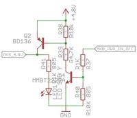
    Using NPN Transistor for PIC-Controlled ON-OFF Switch with VMusic3, Bluetooth, or DAB+ Radio
    Using NPN Transistor for PIC-Controlled ON-OFF Switch with VMusic3, Bluetooth, or DAB+ Radio

    I know that it can be done on one PNP transistor, but unfortunately due to the need to control the signals that enable the multiplexers, it will be easier for me with NPN.
  • ADVERTISEMENT
  • #2 16353362
    RitterX
    Level 40  
    I propose to use ULN2003, ULN2008, ... As the matrix is usually 8 signals, that is, as it found. In addition, you simplify the paths on the board because all the pull-up resistors are already in the chip. The maximum current of 0.5A is sufficient to control the relays, there are also integrated closing diodes for the relays. The input-output of the proposed circuits is deceptively similar to NPN transistors.
  • #3 16353443
    silelis
    Level 12  
    Hmmmm,

    So it's really a Darlington system. :D

    I use the L293D in this system to drive the angular motor and I did not think about this solution, but it seems reasonable, simple and elegant. Thanks for the hint.

    As I understand it, the output of such a system will be the same as my module needs, and if it is larger, the Darlington output will be burned?
  • ADVERTISEMENT
  • #4 16353711
    jarek_lnx
    Level 43  
    silelis wrote:
    I design a PIC-controlled system and I want the transistor to be a kind of relay that turns the power on to equal electronic modules (e.g. VMusic3, Bluetooth, or DAB + MonkeyBoard radio) that are the periphery of the system (controlled by PIC).
    Start by checking what voltage range these modules allow, there are large voltage drops on Darlington, devices powered from 3.3V may not work properly powered by a Darlington where the voltage drop can be 1V

    silelis wrote:
    Will the NPN transistor connection shown in the 2nd picture work and will I have something like an ON-OFF button controlled by the microcontroller output?
    Only if the supply voltage of the microcontroller is equal to the voltage you want to switch on, but even then using a common emitter with PNP instead will be a better solution.
  • #5 16353726
    silelis
    Level 12  
    And the NPN transistor in the free collector system will work? Then I theoretically have 0.7V drops.
    Or as a last resort NPN in a common emitter and collectors should be added to the mass of modules?

    Added after 4 [minutes]:

    And what about the L293 there will also have such high voltage drops?
  • ADVERTISEMENT
  • #6 16354061
    jarek_lnx
    Level 43  
    silelis wrote:
    And the NPN transistor in the free collector system will work? Then I theoretically have 0.7V drops.
    Not free, but a common collector, otherwise an emitter follower, of course, will work, the voltage drop as you write and the base resistor can be removed because in this system the base current regulates itself.

    silelis wrote:
    Or as a last resort NPN in a common emitter and collectors should be added to the mass of modules?
    You can do it, but you have to be careful with the input signals, you cannot give 0V to the input on a module with cut-off ground, because there will be parasitic power supply from this input. A similar problem occurs when cutting off the plus, if you give some voltage to the input when the module is turned off, part of the current will flow to the power supply, so it may work "a little".

    silelis wrote:
    And what about the L293 there will also have such high voltage drops?
    Take a look at the catalog, but I remember they were big.
  • #7 16354095
    silelis
    Level 12  
    Shared, shared. I write from my mobile phone and autocorrect knows better.
    What about the Darlington Sziklai circuit where the NPN is controlled from the MCU and the PNP is driven.

    Are there such integrated circuits? Eg transistors or ladders?
    I'm looking for and somehow I can't find it.
  • ADVERTISEMENT
  • #8 16354417
    RitterX
    Level 40  
    If you want an integrated transistor with resistors in one SMD housing, for example, PDTA124E, PDTC143X, BCR143, BCR108, ... there are many manufacturers of this type of components and the components are quite well available. All to save PCB. ULN2003 may have a darlington but it has very good parameters. In saturation for Ic = 100mA, the voltage drop is 1V.
  • #9 16619153
    silelis
    Level 12  
    I am attaching a link to a nice page about transistors - just right for beginners: Link

Topic summary

The discussion revolves around using an NPN transistor as a relay in a PIC-controlled system to power various electronic modules, including VMusic3, Bluetooth, and DAB+ radio. The user seeks to simplify their circuit design due to space constraints on the PCB. Suggestions include using integrated circuits like ULN2003 or ULN2008, which can handle multiple signals and include built-in pull-up resistors, thus reducing board complexity. Concerns about voltage drops in Darlington configurations are raised, with recommendations for using a common collector configuration to minimize voltage loss. The conversation also touches on the availability of integrated transistors with resistors in a single package to save PCB space.
Summary generated by the language model.
ADVERTISEMENT