logo elektroda
logo elektroda
X
logo elektroda

Connecting Two Networks: Mikrotik Router Configuration for Accessing Network 2 Devices & Servers

WMichał 10578 4
ADVERTISEMENT
Treść została przetłumaczona polish » english Zobacz oryginalną wersję tematu
  • #1 16497178
    WMichał
    Level 32  
    Welcome to the beginning of the small schematic diagram of the network
    Connecting Two Networks: Mikrotik Router Configuration for Accessing Network 2 Devices & Servers

    I want to connect these two networks so that network 1 can access network 2 (server computers, devices).
    Router in network 2 based on DDwrt, network 1 based on Mikrotik, which is configured for ports 1 and 3 without failover.
    I made the physical connection from network 2 to 1 as follows:
    From switch in network 2 to the Mikrotika port (ether 5).
    On Mikrotik, I made the following configuration:
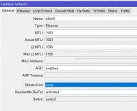
    For port 5 I changed Master Port to none so that DHCP servers do not bite
    Connecting Two Networks: Mikrotik Router Configuration for Accessing Network 2 Devices & Servers
    Then I turned on the dhcp client for this port
    ip dhcp-client add interface=ether3 disabled=no

    Nicely downloaded ip address from network 2:
    [admin@MikroTik] > ip dhcp-client print 
    Flags: X - disabled, I - invalid 
     #   INTERFACE     USE-PEER-DNS ADD-DEFAULT-ROUTE STATUS        ADDRESS           
     0   ;;; defconf
         ether1        yes          yes               bound         XXX.XXX.XXX.XXX/22  
     1   ether3        yes          yes               bound         192.168.1.100/24  
     2   ether5        yes          yes               bound         192.168.2.123/24  
    [admin@MikroTik] > 


    It also added to me from ip routes routing machine
    It looks like this:
    [admin@MikroTik] > ip route print 
    Flags: X - disabled, A - active, D - dynamic, 
    C - connect, S - static, r - rip, b - bgp, o - ospf, m - mme, 
    B - blackhole, U - unreachable, P - prohibit 
     #      DST-ADDRESS        PREF-SRC        GATEWAY            DISTANCE
     0 A S  0.0.0.0/0                          8.8.4.4                   2
     1 X S  0.0.0.0/0                          8.8.8.8                   1
     2 A S  0.0.0.0/0                          8.8.4.4                   1
     3   S  0.0.0.0/0                          8.8.8.8                   2
     4 ADS  0.0.0.0/0                          XXX.XXX.XXX.XXX            1
     5  DS  0.0.0.0/0                          192.168.2.1               1
     6  DS  0.0.0.0/0                          192.168.1.1               2
     7 A S  8.8.4.4/32                         192.168.1.1               1
     8   SB 8.8.4.4/32                                                  20
     9 A S  8.8.8.8/32                         XXX.XXX.XXX.XXX            1
    10   SB 8.8.8.8/32                                                  20
    11 ADC  10.0.0.0/24        10.0.0.1        bridge                    0
    12 ADC  192.168.1.0/24     192.168.1.100   ether3                    0
    13 ADC  192.168.2.0/24     192.168.2.123   ether5                    0
    14 ADC  XXX.XXX.XXX.0/22    XXX.XXX.XXX.XXX   ether1                    0
    [admin@MikroTik] >

    And after that I can ping the 192.168.2.0/24 network from the winbox terminal
    Unfortunately, no device with 10.0.0.0/24 can be pinged to 192.168.2.0/24

    Why is it like that?
    What else should I do to be able to ping network 2 from devices 1 and thus connect to services?
    Is the configuration / approach presented at all ok?

    I drew an external address from the supplier because he doesn't need it.
    If I have to provide something else, please write.
  • ADVERTISEMENT
  • Helpful post
    #2 16497210
    bogiebog
    Level 43  
    WMichał wrote:

    And after that I can ping the 192.168.2.0/24 network from the winbox terminal
    Unfortunately, no device with 10.0.0.0/24 can be pinged to 192.168.2.0/24


    shoot
    192.x network has a gateway not on MT, right?
    so you need to find src-nat connections from 10.x network to 192.x IP address MT (192.xx)
  • ADVERTISEMENT
  • ADVERTISEMENT
  • Helpful post
    #4 16497290
    adamz74
    Level 32  
    It results from the way the IP network works. The selection of the route by individual devices working from the L3 layer (i.e. routers and computers, but not switches and hubs) is made individually based on the routing table (more or less developed). The routing table is created primarily based on the addressing assigned to the device interfaces, static routes (including the default gateway entered), and dynamic routing protocols (if used).

    Looking at your network, e.g. pinging from address 10.0.0.2 to 192.168.2.2 (of course, assuming that there are such addressed devices), it will look like this:
    1. The ping application generated the appropriate icmp package. Now the device looks at address 192.168.2.2 and looks for a matching entry in the routing table. The only entry he finds is default routing or default gateway, which exactly corresponds to the address of the router and the packet is sent there.
    2. Router / Mikrotik receives such a packet and looks at the address again and looks in the routing table. He finds an entry and states that such a subnet is connected directly to its interface. At this time, it can send the packet directly to the device with the address 192.168.2.2.
    3. The device / recipient receives such a package, processes it, prepares a response and tries to send the sender back. He looks at address 10.0.0.2, looks in the routing table and all he finds is the router address, but in this case the router is dd-wrt, so he sends the answer there.
    4. The dd-wrt router receives such a packet, looks at the address, looks in its routing table, and all it finds is the default route towards the Internet. It flies to the router of the Internet provider and here basically ends the life of such a ping response ...

    It is in a nutshell and very simplified.

    By pinging from the router (in this case Mikrotik) addresses from the subnets connected to it, by default ping goes out with the address of the output interface, in this case 192.168.2.123. That is why such ping was successful.

    The simplest solution is to inform the dd-wrt router that traffic to the 10.0.0.0 subnet should send to 192.168.2.123. The situation will be a bit strange, because the one-way traffic will go only through mikrotik and the return traffic will go through dd-wrt and mikrotik.
    Another solution is to use NAT.

    A small note: in this case, addressing the mikrotik with DHCP is not a good idea, because such an address may change and a static entry in the routing table will cease to be valid :(

    Pozdr!
  • #5 16497331
    WMichał
    Level 32  
    Thank you for the extensive explanations.
    I didn't even think about setting up routing to ddwrt as it didn't work.
    For now, dynamic addressing will then of course be static entries.
ADVERTISEMENT