logo elektroda
logo elektroda
X
logo elektroda

12V Electric Motor Speed Controller for Boat: Maximize Efficiency & Reverse Function, 60A Current

zamela 5850 7
ADVERTISEMENT
Treść została przetłumaczona polish » english Zobacz oryginalną wersję tematu
  • #1 16588910
    zamela
    Level 14  
    Hello
    I swim a boat with an electric motor powered by a 12V battery, the problem is quite high power consumption of this engine and frequent damage to the gear switch, so I would like to add a smooth speed control so-called maxymizer.

    12V motor voltage and max current for which the driver would have to be is about 60A
    for this smooth regulation plus change of engine revs left and right revs.

    Does anyone have a proven scheme, a design for such a driver?
  • ADVERTISEMENT
  • ADVERTISEMENT
  • #3 16662598
    zamela
    Level 14  
    I know that there are such sets to buy, but I would prefer to build it myself
  • #4 16665845
    Adam-T
    Level 41  
    zamela wrote:
    I'd rather build it myself

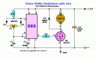
    Here you are:
    12V Electric Motor Speed Controller for Boat: Maximize Efficiency & Reverse Function, 60A Current
  • ADVERTISEMENT
  • #5 16665900
    electronics_design

    Level 14  
    Really great advice ... would put together the elements that are listed there and see only smoke. The BUZ11 transistor has 30 A continuous current, which is half of what the topic founder needs. In addition, with a current of 60 A, the power that will be released on it is 144 W, without experience in constructing converters it will be difficult for you to build a reliable driver. That's why I suggest you buy the link I sent, it will be 100% cheaper
  • #6 16666570
    zamela
    Level 14  
    700 PLN for a driver is a bit much because when I bought a new engine I could pay extra 3 hundred and have smooth regulation.
  • ADVERTISEMENT
  • #7 16666665
    pawelr98
    Level 39  
    Controlling PWM on 555 is not a bad idea.
    You would need several mosfets in parallel because such current is not a leak.

    There are also industrial IGBT bridges but the price is inadequate.

    The Chinese can make this equipment quite cheaply.
    https://www.banggood.com/DC-1050V-60A-3000W-D...oller-12V-24V-48V-p-1062573.html?rmmds=search

    https://www.banggood.com/10-50V-100A-3000W-PW...-Speed-Controller-p-1117519.html?rmmds=search

    The issue of cooling keying transistors.

    The problem will be with reversing the direction of rotation. This second controller simply uses relays. I would have bought the first one, added a fan to cool the transistors and a relay system to reverse the rotation. Soldering wires from below to reduce path resistance.
  • #8 16667601
    Adam-T
    Level 41  
    electronics_design wrote:
    Really great advice ... would put together the elements that are listed there and see only smoke.

    The fact admits to an error. I copied the schema from the search engine without thinking. However, it is a fairly simple system and when used instead of BUZ11 STP80NF06 and instead of MBR1645 e.g. 30CPQ150PBF it should do its job. Of course, STP80NF06 should be equipped with a suitable heat sink, which will disperse about 30W.

Topic summary

The discussion revolves around the need for a 12V electric motor speed controller with a maximum current of 60A for a boat, aimed at improving efficiency and enabling reverse functionality. Users suggest various solutions, including purchasing ready-made controllers and DIY options. One user provides a link to a commercial product, while others discuss the challenges of building a reliable controller, emphasizing the need for appropriate components like MOSFETs and heat sinks. Suggestions include using PWM control with a 555 timer and considering industrial IGBT bridges, although cost is a concern. The conversation highlights the importance of cooling mechanisms and the potential for using relays for reversing motor direction.
Summary generated by the language model.
ADVERTISEMENT