logo elektroda
logo elektroda
X
logo elektroda

VA Transformer Capacity for 24V, 5A Power Supply & LM317 to LM350 Swap Query

carbon_45 4437 18
ADVERTISEMENT
Treść została przetłumaczona polish » english Zobacz oryginalną wersję tematu
  • #1 16618173
    carbon_45
    Level 12  
    Hello to all forum members.
    I want to make a simple power supply with smooth voltage regulation and amps up to 24V and 5A. There are many topics, but they relate to a specific question.
    I was looking for such a power supply on the forum and I found it, but I did not write it down and I missed it. I only had an entry that the description was PE 12/96. It's good that I have archival editions of these magazines and found this power supply. And now I have a specific question. How much does a VA transformer have to be able to withstand the 5A at this voltage of 24V, and can these LM317 be replaced in this project with more powerful LM350.
    In the attachment there is a whole page about this power supply, along with a diagram.
    greetings
    Janusz
  • ADVERTISEMENT
  • #2 16618194
    pawlik118
    Level 33  
    The recommended transformer should have a power of not less than about 24V * 5A * 1.7 = 200VA. Unfortunately, it will be difficult to obtain smooth regulation at 5A current. Let us assume that Uo = 5V. The voltage from the transformer is 24V * 1.41 = 33Vdc. The power lost on the stabilizer will be approximately: P = (33V-5V) * 5A = 140W and will be released in the form of heat. There is no chance that the LM317 or LM350 can generate such power.
  • #3 16618215
    gumisie
    Level 43  
    @ pawlik118 what you wrote is right with a small amendment, most of the power will be dissipated on the MJ4502 transistor and with the appropriate heat sink, such a solution could be used.
  • ADVERTISEMENT
  • #4 16618223
    pawlik118
    Level 33  
    unfortunately i don't have how to open the attachment so i didn't see the schematic, i was only referring to the LM350 without "booster transistors". Nevertheless, 140W is a lot of heat to dissipate. It is worth thinking about some sort of automatics switching the appropriate windings from the transformer. Or buy a ready power supply for PLN 200 :)
  • #6 16618250
    carbon_45
    Level 12  
    Thanks for the answers.
    Tell me what other solution for such a power supply should I choose. I don't really use the 24V ones, only this one was supposed to be used to check 12V bulbs up to 75W
  • #7 16618322
    gumisie
    Level 43  
    carbon_45 wrote:
    this one was supposed to be used to check 12V bulbs up to 75W
    For this purpose (ordinary filament light bulb), a transformer with appropriate parameters, 12V / 100W, is enough.
  • #8 16618370
    carbon_45
    Level 12  
    These 100W correspond to the data from the 200 VA transformer?

    Added after 3 [hours] 51 [minutes]:

    I also wanted to use it as a charger for various batteries, car 12V-14.4V / 4.5A, gel 12V-13.8V / 0.8A, gel 6V-7.2V / 0.4A. I also found a TST100W / 24V toroidal transformer; 100VA; 230VAC; 24V; 4.16A. I wanted to use it as such universal for my purposes.
  • ADVERTISEMENT
  • #9 16618980
    gumisie
    Level 43  
    carbon_45 wrote:
    These 100W correspond to the data from the 200 VA transformer?
    No, not responding because this 200VA (W) transformer corresponds to the calculation given by Kol. pawlik118 in # 2 regarding a transformer with a voltage of 24V and current efficiency of 5A, and would be required for the power supply proposed by you. These 100W (I = 100VA: 12V = 8A) proposed in # 7 concerns: " checking 12V bulbs up to 75W " . As for the so-called "universal rectifier" read on the electrode. There are many topics regarding the rules and requirements that a "charger" should meet for a given type of battery.
    Greetings.
  • ADVERTISEMENT
  • #10 16622368
    carbon_45
    Level 12  
    Hello.
    Thanks for the answers. I found a small transformer with a secondary voltage of 31V, but I don't know how many amps it has, because there is no description on it. I decided to make this ordinary power supply on it, which is attached in the attachment on the LM350. Now, when I started to put elements on the diagram in Eagle, I noticed that there is -6V to pin 4 of the LM301A chip. Is it a negative -6V supply, because it is probably not a mass, it would have a different symbol. I looked for the meaning of the 4 foot in the descriptions and there is Vee. I attach pictures of the schematic of this LM301A
    I have some 1N4004 and 1N4008 diodes. Can I replace them with these 1N457
    greetings
    Janusz

    Added after 2 [minutes]:

    As pictures are added now. I checked add, it appeared in a new window and that was all. What else was I supposed to do, because they are gone.
  • #11 16622574
    gumisie
    Level 43  
    carbon_45 wrote:
    Is it negative power supply -6V,
    Yes it is an extra negative voltage. You can easily replace the 1N457 diodes with those you have as for trfo,
    carbon_45 wrote:
    I found a small transformer with a secondary voltage of 31V, but how many amps it has, I do not know,
    I would apply it:
    carbon_45 wrote:
    I also found a TST100W / 24V toroidal transformer; 100VA; 230VAC; 24V; 4.16A.
    . Additionally, you will be able to add an additional 6V winding.
    Greetings.
  • #12 16626101
    carbon_45
    Level 12  
    Hello.
    I have a technical question. I have already made this PCB, and I always have the problem of not knowing what to put on the board when the element is outside the board on the heat sink and now too. In this case, I mean two elements. The first is the MJ4502 and LM350 transistor. Fixing to the board should be done on soldering points, can I insert a 16A-24A angular terminal block in this place and connect the transistor or thyristor and other elements that are on the external heat sink to this board with the help of bolted wires, or solder these wires to this board. Now I have a question about this LM350 chip. What kind of a large heat sink must it have and whether it also needs to be led outside, and whether one with ATX power supplies, mounted on this board with components, is enough for it.
    greetings
    Janusz
  • #13 16626177
    gumisie
    Level 43  
    Hello.
    With such a large voltage difference U input / min U out. there will be a lot of heat output, so the heat sink should be suitable. All strips provide some resistance, so direct soldering to the PCB is a better solution, also remember to isolate these elements from the heat sink.
  • #14 16626284
    398216 Usunięty
    Level 43  
    gumisie wrote:
    All strips provide some resistance, so direct soldering to the PCB is a better solution
    Sure, soldering will be a better solution, but is it the most convenient? In my humble opinion, it is better to give the ARK connectors on the PCB, for example, and be able to disconnect either the power transistor or the power supply or the output, than to condemn yourself to a spiderweb where any possible repair (hopefully not!) Required desoldering of all wires - and it is more convenient during assembly. .
    Let's not demonize the resistance at the junction = it's not hundreds of amperes and kilowatts of power. For 5A (and even 10) it does not matter whether the junction resistance is 0.001 or 0.01 Ohm.
  • #15 16626354
    carbon_45
    Level 12  
    Thank you for your answer.
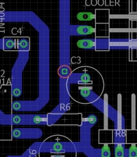
    Now, while browsing the PCB and adding one element (Pinhead 1x3 / 90) to the Cooler, I suddenly found myself on the Drill Size path and I can't remove it. In Tools Errors, he points to him all the time. How can I get rid of something like this from my plate? VA Transformer Capacity for 24V, 5A Power Supply & LM317 to LM350 Swap Query
  • #16 16626465
    398216 Usunięty
    Level 43  
    This is a grommet? "Ripup" this path and lead it again.
    VA Transformer Capacity for 24V, 5A Power Supply & LM317 to LM350 Swap Query
    Unless it is a heat sink mounting - then it is assigned to the heat sink itself in the library and it cannot be done this way. You would have to change the library of this item.
  • #17 16626560
    carbon_45
    Level 12  
    What would I do without your help, nothing. One last question. Does it go somewhere to save the settings permanently, which are made in the diagram in the Grid option. I mean the set size (Size 50 and selected mils), and that these settings should be opened together with the diagram. I have to re-enter these settings every time.
    Janusz
  • #18 16626571
    398216 Usunięty
    Level 43  
    And do you save the project before closing it?
    Click on "file" and then "save". You can also save each version of the project by changing the name - click "save as" - and enter a name other than the previous one.
  • #19 16626713
    carbon_45
    Level 12  
    Every time before closing the program I make a record. There is one more thing. When I close the window after saving, be it a diagram or a boart, I always see a yellow and black line at the top of the window. I click on it and it disappears. What it is supposed to mean, I don't know, because I don't know English.

Topic summary

The discussion revolves around designing a power supply capable of delivering 24V and 5A, with inquiries about the appropriate VA rating for the transformer and the feasibility of substituting LM317 with LM350. It is suggested that a transformer with a minimum rating of 200VA is necessary to handle the power requirements, considering the significant heat dissipation involved. The LM350 can be used, but additional components like MJ4502 transistors may be required for effective heat management. Alternatives for a simpler power supply, such as using a 12V transformer for testing bulbs, are also discussed. The conversation includes technical details about circuit design, heat sink requirements, and component compatibility.
Summary generated by the language model.
ADVERTISEMENT