logo elektroda
logo elektroda
X
logo elektroda

Determining Optimal Resistor Values R1 and R2 for Voltage Divider in Arduino Measurement

guzik121 10194 5
ADVERTISEMENT
Treść została przetłumaczona polish » english Zobacz oryginalną wersję tematu
  • #1 16643529
    guzik121
    Level 10  
    Hello,
    I am asking for a hint regarding the voltage divider.
    I want to measure the voltage of a 12V car battery with the help of Arduino.
    I will use the analog arduino pin and voltage divider as in the diagram.
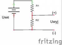
    Determining Optimal Resistor Values R1 and R2 for Voltage Divider in Arduino Measurement
    When calculating the R1 and R2 resistor, I assumed that the maximum Uwe is 15V, and Uwy is to be 5V.
    Thanks to the program "Electronics assistant 2.2.5" I calculated that if R1 = 2 then R2 = 1 but they are not the resistor values but the ratio R1 to R2.
    Question:
    What should be the resistors R1 and R2? What order of magnitude Ohm, kOhm, MOhm?
    For the tests I took R1 = 20kOhm and R2 = 10kOhm and it works, but what should be the most optimal sizes of R1 and R2 resistors.
    Thanks in advance.
    Do you have a problem with Arduino? Ask question. Visit our forum Arduino.
  • ADVERTISEMENT
  • #2 16643658
    LA72
    Level 41  
    20kOm and 10 kOm resistors are correctly calculated.
  • ADVERTISEMENT
  • #3 16643689
    cyann
    Level 20  
    Aim somewhere in the kiloom range. The values you propose will be approx.
  • ADVERTISEMENT
  • #4 16643706
    Defensore.Puniti
    Level 11  
    Hello,
    guzik121 wrote:
    Hello,
    I am asking for a hint regarding the voltage divider.
    I want to measure the voltage of a 12V car battery with the help of Arduino.
    I will use the analog arduino pin and voltage divider as in the diagram.
    Determining Optimal Resistor Values R1 and R2 for Voltage Divider in Arduino Measurement
    When calculating the R1 and R2 resistor, I assumed that the maximum Uwe is 15V, and Uwy is to be 5V.
    Thanks to the program "Electronics assistant 2.2.5" I calculated that if R1 = 2 then R2 = 1 but they are not the resistor values but the ratio R1 to R2.
    Question:
    What should be the resistors R1 and R2? What order of magnitude Ohm, kOhm, MOhm?
    For the tests I took R1 = 20kOhm and R2 = 10kOhm and it works, but what should be the most optimal sizes of R1 and R2 resistors.
    Thanks in advance.
    it all depends on how it is value of input resistance R IN the above analog input pin to which this input will be supplied voltage from this divider.
    It is practically accepted that value of equivalent resistance R WITH resistance divider, and seen from that pin towards the divider resistors should be at least one hundred times smaller from R IN .
    And the value R WITH - using your designation of the divider resistors - is:
    R WITH = 1 / (1 / R 1 + 1 / R 2 ) , this is their parallel connection.
    And then, since; R 1 = 2 o R 2 , we have:
    R WITH = 1 / (1 / (2 o R 2 ) + 1 / R 2 ) = R 2 / (1/2 + 1/1) = R 2 / ((1 + 2) / 2) = R 2 o (2/3) , i.e.
    R 2 = (3/2) o R WITH .
    But if it is to be:
    R WITH = (1/100) o R IN then we have:
    R 2 = (3/2) o (1/100) o R IN .
    You still have to count for yourself because I don't know the value of the input resistance R IN .
    Of course,
    R 1 = 2 o R 2 .

    greetings
  • ADVERTISEMENT
  • #5 16782564
    guzik121
    Level 10  
    Hello,
    I have one more question.
    The system from the first post works perfectly provided that the voltage from the battery from which the arduino is powered is measured.
    How to measure the voltage from several batteries with arduino, e.g. 2, if the arduino itself will be powered separately from a 9V battery.
    Thank you in advance for the hint.
  • Helpful post
    #6 16782577
    zster

    Level 28  
    Same :) You make a voltage divider calculated so that its output never exceeds 5V, minus these batteries you connect to the Arduino ground and plus to the voltage divider input.
ADVERTISEMENT