logo elektroda
logo elektroda
X
logo elektroda

Optimal Load Value for Battery Tester Simulating Vehicle Start-Up Conditions

zasilaczen 8352 14
ADVERTISEMENT
Treść została przetłumaczona polish » english Zobacz oryginalną wersję tematu
  • #1 16653127
    zasilaczen
    Level 8  
    Hello
    I need a simple tester to check the dry condition of the batteries.
    The tester is to simulate the start of the car if the battery voltage does not drop below 10V.
    Construction: a piece of wire on the section of which resistors or other components giving an artificial load will be attached.

    The problem is choosing the right load value. I have browsed a few topics with inrush current and some say that the starter takes 100-150A from the battery, and others that 300-350A.
    Another problem is that at the moment of start-up, these values jump significantly because many factors of work change, and with such an artificial load, the current is constant.

    What value will be the most optimal for such a test?
    On the one hand, I want to get a strong load so that the measurement is reliable, and on the other hand, I don't want to finish the battery.
    I will add that the measurement length would take about 5 seconds for the multimeter to have a moment to stabilize the values.
  • ADVERTISEMENT
  • Helpful post
    #2 16653155
    eumox
    Level 13  
    Hello
    Original testers available for purchase load 100A or 125A
    greetings
  • #3 16653170
    zasilaczen
    Level 8  
    This is already concrete, thank you
  • ADVERTISEMENT
  • #4 16653222
    funak
    Level 27  
    It should be realized that to load 350A you have to take into account the power of 4.2kW.

    For example, if you load a copper wire of an appropriate length, its temperature will change for a few seconds, which will cause the resistance to change as well.

    Maybe I would focus on 100W resistors.
    For example like this:

    Such a resistor can be loaded 5x with a time of 5 seconds, which gives us 500W / piece.
    http://www.tme.eu/pl/details/ax100wr-0r47/rezystory-100w/te-connectivity/5-1625999-3/

    Counting on ...


    470mOhm, it gives it at:
    = 10V, current: 21A, power 212W
    = 12.6V, current: 27A, power 340W

    220mOhm, it gives it at:
    = 10V, current: 45A, power 454W
    = 12.6V, current: 57A, power 718W
    Here, the activation time is max. 3.5 seconds.

    Connect the load with a car relay, each resistor separately - for example a time relay.
  • #5 16653292
    Strumien swiadomosci swia
    Level 43  
    Probably wind a few turns of steel wire cooled with a PC 12V fan.
  • ADVERTISEMENT
  • #6 16653363
    Anonymous
    Anonymous  
  • #7 16653406
    Anonymous
    Level 1  
  • ADVERTISEMENT
  • #8 16653408
    Aleksander_01
    Level 43  
    It will be cheaper to buy a new one (100 A) for up to PLN 100, or a stimulant (professional equipment 150/300 A) for about PLN 250.

    I would like to make a 100 ? resistor with a power of 0.1 W, but the cost is about 14 cents and in the store they are 10 cents. Advise on how to go below 10 cents, I need two such resistors.
  • #9 16653503
    vodiczka
    Level 43  
    zasilaczen wrote:
    I have browsed a few topics with inrush current and some say that the starter takes 100-150A from the battery, and others that 300-350A.
    Both are right. It depends on the engine model and temperature at start-up.
    zasilaczen wrote:
    I will add that the measurement length would take about 5 seconds for the multimeter to have a moment to stabilize the values.
    Longer than normal boot time? 3 seconds is enough to stabilize the measurement result, unless you want to check if the voltage above 10V is maintained for at least 5s.
    zasilaczen wrote:
    What value will be the most optimal for such a test?
    The value will depend on the rated inrush current of the battery under test.
    Do you want to test "so-so" or according to the standard? The standard specifies the method of performing the measurement.
  • #10 16653565
    zasilaczen
    Level 8  
    So yes gentlemen.
    I will aim at 125A, i.e. how well I counted 1500W.
    On resistors, it would definitely work fine, but the cost of three is almost PLN 100.
    The scale of my needs is also not such that I should immediately obtain a professional tester.
    I am more inclined towards something "Home Made". I have workshop facilities, so there is nothing to prevent me from doing something like this myself, I just need your substantive help to make it all have hands and feet.

    The idea with wire is nice, but I'm afraid it will have to be a lot to get this load, and I need something more handy.

    The idea with sheet metal is equally interesting, but I am not an electronics engineer and I do not know how 60m? is up to 125A

    I really like the idea of glow plugs, small, handy and power-hungry, this could be it :) 5 seconds of connect should be enough. Describe something more about it and how you have built the structure

    @vodiczka Tester is only to exclude batteries where the voltage drops below 10V. For more accurate measurements, I would already invest in a testing device.
  • #11 16653647
    mkpl
    Level 37  
    To test the condition of the battery, it is not necessary to load it with electricity. You have to measure its internal resistance. Then you can easily determine the starting current and the condition of the battery very accurately. A healthy battery is approximately 3 to 5 mOhm which gives a starting current of approximately 350A.

    Good quality testers measure the voltage difference with no load and with a load of about 10A and from this they determine the internal resistance and the possible starting current. Even better instruments, e.g. Hioki, measure the battery resistance for 1kHz AC current and do not require any current load (but the cost is considerable).

    It should also be remembered that the "starting" current given on the battery is the maximum permissible current, which in a sufficiently short time (specified in the standard which is written opposite) allows to charge the battery without damaging it. Otherwise, the lead connectors between the cells will burn out or the lead plates will bend.
  • #12 16653663
    kkknc
    Level 43  
    I do not see any sense with the construction. You have ready both load and newer electronic ones. Cheap as dirt, so why bother and think about it.
    The cheapest electronics are $ 20 with a $ 30 resistor. So what will you build below PLN 100?
  • #14 16654261
    sebap
    Level 41  
    On the well-known Yato auction site, you can buy for less than PLN 100, I do not see any sense in DIY in this case.
  • #15 16755380
    Adamcyn
    Level 38  
    Do not read the voltage during the test with the built-in voltmeter - it lowers the measurement.
    Measure with a separate multimeter directly at the battery poles.
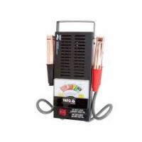
    However, the built-in resistor actually has the value of 0.12 ?, i.e. a load of about 100 A.
    This applies to my tester similar to this one:

    Optimal Load Value for Battery Tester Simulating Vehicle Start-Up Conditions

Topic summary

The discussion revolves around determining the optimal load value for a battery tester designed to simulate vehicle start-up conditions without excessively draining the battery. Users suggest various approaches, including using resistors, steel wire, and glow plugs to create the necessary load. The consensus indicates that a load of around 100A to 125A is suitable for testing, with considerations for the power ratings of components used. Some participants emphasize the importance of measuring internal resistance to assess battery health accurately, while others advocate for purchasing ready-made testers due to cost-effectiveness. The conversation highlights the balance between achieving a reliable measurement and avoiding battery damage during testing.
Summary generated by the language model.
ADVERTISEMENT