logo elektroda
logo elektroda
X
logo elektroda

230VAC voltage measurement with Atmega / Arduino optoisolation

wojtek6000 13896 8
ADVERTISEMENT
Treść została przetłumaczona polish » english Zobacz oryginalną wersję tematu
  • #1 16762316
    wojtek6000
    Level 9  
    Hello

    I would like to build the simplest system that allows measuring AC voltage in the socket, so that I can read it through the ADC converter in the Atmega8 microcontroller. I want the system not to have a transformer. I would also like to have galvanic separation. At the moment, I was able to come up with something like this:

    230VAC voltage measurement with Atmega / Arduino optoisolation

    Resistors R15 and R16 are 2W and have 100kOhm each.
    P8 leads to the ADC input of the microcontroller.

    Is it possible to measure AC voltage with an accuracy of ~ 5V through this system?
    Do you have a problem with Arduino? Ask question. Visit our forum Arduino.
  • ADVERTISEMENT
  • #2 16762356
    czareqpl
    Level 33  
    wojtek6000 wrote:
    circuit enabling the measurement of alternating voltage in the socket

    If it's alternating.

    wojtek6000 wrote:
    Is it possible to measure AC voltage with an accuracy of ~ 5V through this system?


    No.
    I don't know why this 100uF capacitor. Charging via a 4k7 resistor will take a long time ...
  • ADVERTISEMENT
  • #3 16762371
    wojtek6000
    Level 9  
    Hmm ... what if I gave up optoisolation and left only R15, R16 and diode? It won't be safe for a microcontroller, but will I get the desired effect then?
  • ADVERTISEMENT
  • #4 16762394
    czareqpl
    Level 33  
    You should not give up galvanic isolation. It can also be dangerous for the programmer and the computer, ending with you.

    Galvanic separation using a tiny transformer is strongly recommended here.
  • #5 16762446
    wojtek6000
    Level 9  
    So the solution that allows for a "fairly accurate" measurement of 230V alternating voltage is the system from the attachment? The resistor and capacitor would have to be selected depending on the transformer used.

    230VAC voltage measurement with Atmega / Arduino optoisolation
  • Helpful post
    #6 16762492
    czareqpl
    Level 33  
    wojtek6000 wrote:
    So the solution that allows for a "fairly accurate" measurement of 230V alternating voltage is the system from the attachment?


    No. The circuit from the attachment measures DC voltage and not AC voltage. Why did you give diodes and a capacitor? To measure alternating voltage?

    Use one of the transformer terminals to ground the microcontroller circuit, from the other lead the diode in the direction of conduction to the microcontroller. Behind the diode, give a resistor divider so that it has a voltage drop on it that will not kill your microcontroller (0-5V + surge supply). With this system you will be able to make single-phase alternating voltage measurements. So with a diode you cut off the positive part of the sine. It is then easy to measure the frequency, effective and maximum value.
  • #7 16762547
    wojtek6000
    Level 9  
    Is this system correct so that I can measure the RMS voltage? I know that I will have to add a piece of code that calculates it, but I can handle it :)

    230VAC voltage measurement with Atmega / Arduino optoisolation
  • ADVERTISEMENT
  • Helpful post
    #8 16762759
    czareqpl
    Level 33  
    I think it will do. The pin which you marked ADC is best checked with an oscilloscope before connecting to the microcontroller. If it does not exceed the permissible voltage, it will be ok. To be sure, you can still give a 470Ohm resistor in series, followed by a zener diode opposite 3.6V or 5.1V. This will protect your circuit against overvoltages, however, it can introduce distortions in the measured signal.
  • #9 16778434
    wojtek6000
    Level 9  
    I was able to design the system and write a program to measure the effective voltage from eight channels with the help of an analog multiplexer CD4051B. In another thread I found information that in order to determine the rough value of the effective voltage you should multiply the peak voltage by the square root of 2. So I did. However, I have a problem. The system without connecting any test leads indicates correctly 0V, but after connecting the cable with 230VAC voltage to one of the eight TEZ 1.5 / D 230/6 transformers, the system reads at the 169V input, and on other unconnected it indicates about 16V. What could be wrong? Below is the program and circuit diagram (resistors in the dividers are 4.7k).
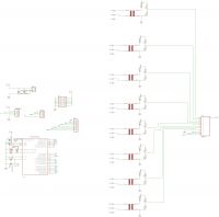
    230VAC voltage measurement with Atmega / Arduino optoisolation
    [code:1:d5ce73d7f3]

    #define WA A1
    #define WB A2
    #define WC A3

    void setup() {
    // put your setup code here, to run once:
    pinMode(A0,INPUT);
    pinMode(WA,OUTPUT);
    pinMode(WB,OUTPUT);
    pinMode(WC,OUTPUT);
    Serial.begin(9600);
    }

    /*
    * ustawieniee kanału multipleksera
    */
    void set_kanal(byte nr){
    switch(nr){
    case 0:{set_0();}break;
    case 1:{set_1();}break;
    case 2:{set_2();}break;
    case 3:{set_3();}break;
    case 4:{set_4();}break;
    case 5:{set_5();}break;
    case 6:{set_6();}break;
    case 7:{set_7();}break;
    default:{res();}break;
    }
    delay(20);
    }

    void set_0(){
    digitalWrite(WA,LOW);
    digitalWrite(WB,LOW);
    digitalWrite(WC,LOW);
    //Serial.print("Odczyt z zero:\t\t");
    }

    void set_1(){
    digitalWrite(WA,HIGH);
    digitalWrite(WB,LOW);
    digitalWrite(WC,LOW);
    //Serial.print("Odczyt z jeden:\t\t");
    }

    void set_2(){
    digitalWrite(WA,LOW);
    digitalWrite(WB,HIGH);
    digitalWrite(WC,LOW);
    //Serial.print("Odczyt z dwa:\t\t");
    }
    void set_3(){
    digitalWrite(WA,HIGH);
    digitalWrite(WB,HIGH);
    digitalWrite(WC,LOW);
    //Serial.print("Odczyt z trzy:\t\t");
    }
    void set_4(){
    digitalWrite(WA,LOW);
    digitalWrite(WB,LOW);
    digitalWrite(WC,HIGH);
    //Serial.print("Odczyt z cztery:\t\t");
    }
    void set_5(){
    digitalWrite(WA,HIGH);
    digitalWrite(WB,LOW);
    digitalWrite(WC,HIGH);
    //Serial.print("Odczyt z piec:\t\t");
    }
    void set_6(){
    digitalWrite(WA,LOW);
    digitalWrite(WB,HIGH);
    digitalWrite(WC,HIGH);
    //Serial.print("Odczyt z szesc:\t\t");
    }
    void set_7(){
    digitalWrite(WA,HIGH);
    digitalWrite(WB,HIGH);
    digitalWrite(WC,HIGH);
    //Serial.print("Odczyt z siedem:\t\t");
    }
    void res(){
    digitalWrite(WA,LOW);
    digitalWrite(WB,LOW);
    digitalWrite(WC,LOW);
    delay(5);
    }

    double get_voltage(){
    long czas_start=millis();
    long teraz=0;
    int _max=0;
    int pomiar=0;
    while(teraz_max){
    _max=pomiar;
    }
    }
    return map(_max,0,1024,0,240)/sqrt(2); //obliczenie watości skutecznej
    }

    void loop() {
    for(byte i=0;i

Topic summary

The discussion revolves around designing a system to measure 230VAC voltage using an Atmega8 microcontroller without a transformer, while ensuring galvanic isolation. Initial suggestions included using resistors and capacitors, but concerns about safety and accuracy led to recommendations for incorporating a transformer for isolation. A proposed circuit was discussed, which involved using a diode and resistor divider to safely measure AC voltage. The author later confirmed the design's functionality with an analog multiplexer (CD4051B) for multiple channels but encountered issues with incorrect voltage readings, prompting further troubleshooting of the circuit and code.
Summary generated by the language model.
ADVERTISEMENT