FAQ
TL;DR: Building an LM338 bench PSU? Note this expert warning: “current limitation will not work at low voltage (below about 1.4 V).” That single fact shapes safe resistor choices, 0 V output goals, and current‑limit behavior. [Elektroda, jta, post #16777671]
Why it matters: You’ll avoid smoked loads and design a supply that actually hits 0 V and regulates current where it counts. This FAQ is for DIYers tuning 1.25–30 V, 0–3 A LM338 supplies who want reliable coarse/fine adjustment and protection.
Quick Facts
- LM338’s internal limit won’t act properly below ~1.4 V output; plan for this in low‑voltage testing. [Elektroda, _jta_, post #16777671]
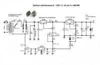
- Adding a small negative rail enables true 0 V output and low‑voltage current regulation. [Elektroda, _jta_, post #16782259]
- R2≈150 Ω can serve as the current‑set potentiometer in the shown scheme. [Elektroda, Anonymous, post #16782561]
- For coarse/fine control: add a fine pot in series at ~10% of the main pot’s value. [Elektroda, Anonymous, post #16783409]
- LM338 includes short‑circuit/thermal protection, though behavior changes if you add external pass transistors. [Elektroda, _jta_, post #16781501]
Can I get true 0 V output from an LM338 supply?
Yes, but not from a single positive rail alone. You need a small auxiliary negative rail. It lets the adjust node go below ground so the output reaches 0 V. It also helps the current limiter work at very low outputs. “This negative voltage enables output voltage adjustment from 0.” [Elektroda, jta, post #16782259]
Why does current limiting fail near 0–1.4 V?
The LM338’s internal circuitry needs headroom to sense and limit current. Below about 1.4 V at the output, the limiter behavior degrades. Designers often add a negative rail so sensing and control have margin at low voltages. Quote: “current limitation will not work at low voltage (below about 1.4 V).” [Elektroda, jta, post #16777671]
Which potentiometer sets current in the shared schematic?
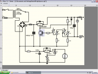
In the discussed layout, the R2 ≈150 Ω potentiometer adjusts the current limit. Keep its wiper leads short and add a small series resistor to prevent hard zero. That stabilizes adjustment and protects the wiper. [Elektroda, Anonymous, post #16782561]
How do I add coarse and fine voltage knobs?
Place a second potentiometer in series with the main voltage pot. Size the fine pot to about 10% of the main pot’s value. This gives smooth trimming without making the range twitchy. Keep both pots’ end terminals solidly tied to the same nodes. [Elektroda, Anonymous, post #16783409]
Is there another way to wire dual pots on LM338?
You can put the two pots in parallel, then route each wiper to ADJ through different resistors (e.g., 100 Ω from the current pot, 2 k from the 2k2 pot). This shapes ranges and improves stability. Avoid connecting ADJ directly without those series resistors. [Elektroda, jta, post #16783627]
Does LM338 have built‑in short‑circuit protection?
Yes. LM338 integrates current limiting and thermal shutdown to protect itself. Protection behavior changes if you add an external pass transistor; then the IC may survive while the transistor doesn’t. Keep that in mind during expansions. [Elektroda, jta, post #16781501]
Will built‑in protection still work with an external pass transistor?
No, not as you expect. The LM338 protects itself, but an external pass transistor can conduct destructive current during a fault. Add separate current‑sense and protection around the pass device if you extend output current. [Elektroda, Anonymous, post #16781552]
Are four adjustment pots necessary?
Not usually. Use one pair for voltage (coarse/fine) and one pair for current (coarse/fine). Extra pots complicate tuning without benefit. “I would already understand two, coarse and fine regulation, but four?” [Elektroda, Anonymous, post #16781852]
Is the auxiliary negative rail risky for connected devices?
It can be if miswired. The auxiliary negative supply can stress the load during faults or reference shifts. Implement proper grounding, output sensing, and protection to avoid injecting the negative rail into the DUT. Treat it with caution. [Elektroda, Anonymous, post #16782067]
How can I achieve current regulation starting at 0 A?
With LM338 alone, it’s hard. Designers use a small negative rail and suitable sense network, or choose an IC that natively supports 0 A regulation. L200 is a classic option when you need flexible current/voltage control. [Elektroda, Anonymous, post #16781552]
What pre‑regulator idea can cut heat and improve stability?
Consider the LT1083 datasheet’s pre‑regulator approach. It’s more complex but worth building for better thermal performance and dynamic response. Use it to drop most of the voltage before the main regulator stage. [Elektroda, Freddy, post #16782276]
My design won’t regulate from 0 V or low current—what’s wrong?
That’s expected with a basic LM338 setup. It won’t regulate from 0 V, and current limiting degrades below ~1.4 V. Add a negative rail or redesign the control loop to maintain headroom. Confirm your sense resistor wiring and reference points. [Elektroda, jta, post #16777671]
What resistor values help stabilize the ADJ node with two pots?
Route each wiper to ADJ through resistors (example: 100 Ω from the 150 Ω current pot, 2 k from the 2k2 voltage pot). This prevents interaction and keeps fine control linear. Avoid direct wiper‑to‑ADJ connections. [Elektroda, jta, post #16783627]
Do I have to buy a ready‑made supply instead of building?
Buying is simpler, but building teaches and customizes features. If you build, plan for safe low‑voltage behavior, heat, and protection. A commercial 30 V/5 A unit exists, but the OP chose to DIY for learning and satisfaction. [Elektroda, Daniel.1990, post #16777740]
What’s an easy 3‑step way to add fine voltage control?
- Insert a fine pot in series with the main voltage pot.
- Size it to ~10% of the main pot’s value.
- Keep wiring short; verify end‑to‑end resistance and range before power‑up. [Elektroda, Anonymous, post #16783409]
Any gotchas when testing below 1.5 V and above 2 A?
Yes. Expect weak current limiting below ~1.4 V unless you add a negative rail. Also note layout and cooling matter when sourcing multi‑amp loads. One post flags issues starting around 0.66 A if the scheme is not optimized. [Elektroda, jta, post #16777671]


