FAQ
TL;DR: Use two automotive relays, NC limit switches, and a Left–0–Right selector; a wiper motor draws “a little more than 1A.” [Elektroda, dioda1000, post #16831255]
Why it matters: This setup safely reverses a 12V wiper motor, protects contacts, and prevents overtravel in DIY actuators.
Quick Facts
- Recommended topology: 2 relays for direction, limit switches carry only coil current, not motor current. [Elektroda, 266564, post #16831367]
- Fuse guidance: ~1 A in control circuit; 7.5–10 A in motor circuit for protection. [Elektroda, 266564, post #16831367]
- Relay pinout tip: motor to both 30s; +12V to 87 and 87a on each relay. [Elektroda, 266564, post #16831472]
- Use NC (normally closed) limit contacts for protruding end-stops. [Elektroda, 266564, post #16831472]
- Avoid 19V laptop PSUs; choose a 12V supply for wiper motors. [Elektroda, 266564, post #16832042]
How do I wire a 12V wiper motor with a Left–0–Right switch and two limit switches?
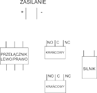
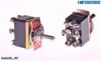
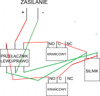
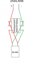
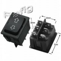
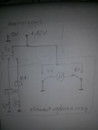
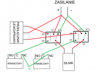
Use a Left–0–Right selector to drive two relays. Put the limit switches in series with the relay coils so only small control current passes through them. Let the relay contacts handle the motor current. This improves reliability and reduces switch wear in continuous use. Automotive relays are inexpensive and well-suited. “Each of these three will work,” but the 2‑relay approach is best for longevity. [Elektroda, 266564, post #16831367]
Which relay terminals go where for reversing the motor?
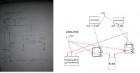
Wire the motor between terminal 30 on both relays. Feed +12 V to terminals 87 and 87a on both relays. This establishes opposite polarities to the motor depending on which relay you energize, giving forward or reverse. Confirm your relay pinout matches standard automotive layouts before power-up. [Elektroda, 266564, post #16831472]
Should my limit switches be NO or NC?
Use NC (normally closed) contacts when using protruding mechanical end-stops. In NC, a broken wire or failed switch defaults to open, stopping movement safely. With NO, the actuator might not stop until overtravel occurs. “Terminals on NC contacts and not NO if end stops are protruding.” [Elektroda, 266564, post #16831472]
Do I need diodes, and how strong should they be?
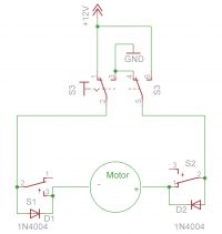
Yes—include suitable diodes to handle the inductive load and protect contacts. The wiper motor draws a little over 1 A, so choose diodes and any suppression components rated for that current and expected surges. Also ensure your limit switches are rated for the expected current if they carry more than coil current. [Elektroda, dioda1000, post #16831255]
What current does a typical wiper motor draw here?
Expect a little over 1 A in this forum-tested setup. Size wiring, diodes, and contacts accordingly, and allow margin for startup surges. Keep runs short to minimize voltage drop. Always verify your specific motor since models vary. [Elektroda, dioda1000, post #16831255]
Can I power the system from a 19V, 3.5A laptop charger?
No. Use a 12 V supply designed for automotive loads. Overvoltage can overheat the motor, stress relays, and trigger violent stops at the limits. Choose a regulated 12 V source with adequate current capability instead. [Elektroda, 266564, post #16832042]
What fuses should I install?
Add two fuses: about 1 A for the control circuit and 7.5–10 A for the motor circuit. This protects small wiring and relay coils while guarding the high-current path. Place fuses close to the power source for best protection. [Elektroda, 266564, post #16831367]
How can I build an auto-reversing drive with just a push switch?
You can use a single push switch plus limit switches so the motor moves to one end, stops, then reverses. This keeps direction consistent on each cycle regardless of start position. It simplifies controls at the expense of manual direction choice. [Elektroda, michalek1988, post #16831072]
What’s the simplest working wiring if everything is in one room?
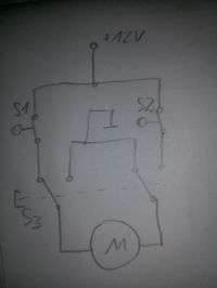
Several diagrams work, including minimalist versions without LEDs. However, if you want long, reliable service, pick the two‑relay solution so small switches only carry coil current and relays carry motor current. “Each of these three will work.” [Elektroda, 266564, post #16831367]
How do NO and NC contacts differ on limit switches?
NO (normally open) contacts close when actuated; NC (normally closed) contacts open when actuated. Use NC for safety so a broken wire or failed switch opens the circuit and stops motion. Match contact type to your mechanical end-stop style. [Elektroda, michalek1988, post #16831072]
What happens if I wire the limit switches incorrectly?
Using NO contacts with protruding end-stops can fail to cut power until after overtravel, risking mechanical damage. Choose NC contacts for protruding stops. Verify switch function with a meter before powering the motor to avoid surprises. [Elektroda, 266564, post #16831472]
Give me a quick 3‑step how‑to for the 2‑relay driver.
- Use a Left–0–Right selector to energize relay coils for direction.
- Put both limit switches in series with the coil circuit so they interrupt control current.
- Route all motor current through relay contacts; keep the selector and limits as low-current controls. [Elektroda, 266564, post #16831367]
Are my small micro‑limit switches OK for this project?
Yes, if they only carry relay coil current. The two‑relay design keeps heavy current in the relay path. If you wire motors directly through limits, ensure their current rating exceeds your motor draw plus surge. [Elektroda, 266564, post #16831367]
Any final check before power‑up?
Confirm motor leads on both 30s, +12 V on 87 and 87a, and NC wiring on the limits. Manually actuate each limit to verify it opens the coil circuit. Only then apply power with the selector at 0. [Elektroda, 266564, post #16831472]


