logo elektroda
logo elektroda
X
logo elektroda

Circuit Theory: Clarifying Source Power & Calculating No-Load Voltage with Thevenin's Theorem

7833 16
ADVERTISEMENT
Treść została przetłumaczona polish » english Zobacz oryginalną wersję tematu
  • #1 16898128
    Anonymous
    Level 1  
  • ADVERTISEMENT
  • Helpful post
    #2 16898183
    Anonymous
    Level 1  
  • ADVERTISEMENT
  • #3 16898205
    Anonymous
    Level 1  
  • #4 16901995
    kozi966
    Moderator of Electricians group
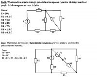
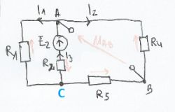
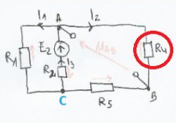
    Thevenin's theorem is that you "cut" the branch in which you want to count something (in this case I3 current).
    From the point of view of this cut branch, you count the resistance for shorted voltage sources in the remaining circuit "after cutting" (in this case, one will remain ...).
    Then you calculate the voltage at the terminals from which you cut the branch (i.e. the voltage drop from the only source - on the resistance R4). So "we roll the circuit and develop."
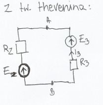
    Having the voltage on the terminals, the replacement resistance, you substitute it as a new system with series connected: voltage source and resistance that you have just calculated.
    You now "add" a cut branch to their terminals and you have a simple circuit with a source voltage difference and two resistances.
  • #5 16904424
    Anonymous
    Level 1  
  • #6 16904434
    kozi966
    Moderator of Electricians group
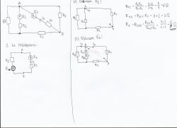
    You have calculated the replacement resistance,
    Now it's time to count the voltage in this system.
  • ADVERTISEMENT
  • #7 16904471
    Anonymous
    Level 1  
  • ADVERTISEMENT
  • #8 16904670
    kozi966
    Moderator of Electricians group
    Erwin14 wrote:
    is it best to count and paste it here?

    With all due respect, but you must be kidding. Should I write the exam for you?

    I do not understand what you have a problem with when counting currents and voltages from one source.
    Since you only have E2, you add the resistances R4 and R5, then connect them in parallel with R1, and then in series with R2. Then pure oma law, and again we develop the circuit to find currents I1 and I2 (although here instead of currents, you immediately have the voltage on the corresponding elements).
  • #9 16904771
    Anonymous
    Level 1  
  • Helpful post
    #10 16904836
    kozi966
    Moderator of Electricians group
    Erwin14 wrote:
    Is this the current I3 and the end of the task?

    No and no.
    So far, we have not yet come to the use of Thevenin's Theorem to the end.
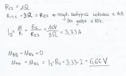
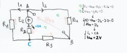
    Now count the I2 current in your configuration. Multiply it by the resistance R4 and you have a voltage drop on the element that interests us (i.e. you are able to calculate the Uab voltage).
    Having the Uab voltage, having a substitute resistance, you have to make a substitute circuit to which you attach the previously cut branch, here:

    Circuit Theory: Clarifying Source Power & Calculating No-Load Voltage with Thevenin's Theorem

    This shows that it's bad You have marked current I3 at the moment.
  • #11 16906351
    Anonymous
    Level 1  
  • Helpful post
    #12 16906525
    kozi966
    Moderator of Electricians group
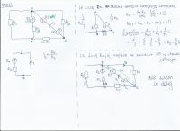
    Unfortunately .... it's not good. The equivalent resistance seen from the viewpoint of terminals A and B is 6/5 ohms. As you stated in post # 5.
    In post # 9 is good. Because in post 9 you count the "second" system, with the 6V source cut out.
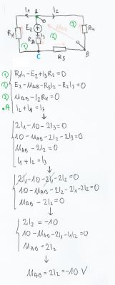
    You have calculated a replacement circuit with a 10V source (where the 3A source current comes out). You just need to develop it to know the voltage drop at the extreme right resistance:

    Circuit Theory: Clarifying Source Power & Calculating No-Load Voltage with Thevenin's Theorem

    If you know this voltage drop, this voltage drop is your substitute voltage in the Thevenin system.

    Only after that you create another layout to count, the one from post number # 10.

    PS
    In the circuit from post # 9 you have the error that you marked the current I3 as a current in the branch with a 10V source. Only that in the task, the current I3 (the correct one to count) is the current in the cut branch with a 6V source. From here you can get "mixed up".
  • #13 16908741
    Anonymous
    Level 1  
  • #14 16908856
    kozi966
    Moderator of Electricians group
    Near!
    Just look at the direction of tensions ... they won't add up.
  • #15 16908889
    Anonymous
    Level 1  
  • #16 16908926
    kozi966
    Moderator of Electricians group
    That's right
  • #17 16909148
    Anonymous
    Level 1  

Topic summary

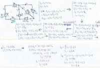
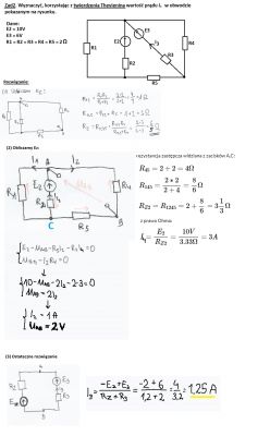
The discussion revolves around solving circuit theory problems using Thevenin's Theorem, specifically focusing on calculating source power and no-load voltage. The user initially miscalculated the current in a branch with a voltage source, leading to confusion about the source current. Participants clarified that the source current is distinct from the current in the branch with the source. The conversation progressed to calculating equivalent resistance and no-load voltage, with various methods discussed, including Kirchhoff's equations. Ultimately, the correct current (I3) was determined to be 1.25 A, and the no-load voltage (Ez) was calculated as 2 V. The final solutions were compiled for future reference.
Summary generated by the language model.
ADVERTISEMENT