Good morning,
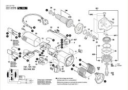
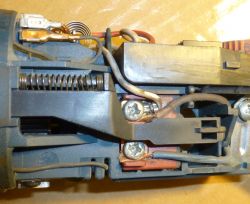
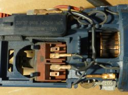
I purchased (one or two years ago) a used Bosch GWS 850 CE angle grinder (06013787AC). The grinder worked and the speed control worked too. Several months have passed since the last time the grinder was turned on. This week I wanted to cut something in the plastic element, and here is an unpleasant surprise - the grinder does not show any signs of life. I turned it on, the photos below show how the individual elements are connected. I found a Bosch schematic of this hardware and am a little confused. I think the connections in my grinder are different than in the diagram. And now I don't know if I can make the connection as shown in the diagram. :
1. If the connection in the device worked, is it correct or acceptable?
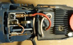
a) for example: the regulator from diagram (No. 51), wire D (red, photo 1) in my device is connected where in the diagram the G wire is to be connected to the brush, and importantly, wire D (red) in my device, it looks like it has a pre-tightened bar and it will definitely not reach where the diagram shows (i.e. to the switch position D on the diagram),
b) cable C from the stator according to the diagram is to be connected to the switch, and in my case it is to the pin on the speed controller next to the G cable (in photo 1 next to the black one on the controller),
c) from the speed controller in my grinder, the G cable is connected where the diagram shows position E and F on the switch, and not to the "upper" brush, as in the diagram,
d) I do not know whether to list further, it seems to me that the photos are legible (unfortunately the person / s who would like to help would have to carry out such an analysis based on the photos and diagram posted, an analysis from which, unfortunately, I am not currently able to draw some constructive conclusions).
2. In the diagram, there is an alternative capacitor (item 12 in the diagram), and I am not. Could it really not be?
"I would give my head" that I did not lend anyone a grinder and since it is in my hands, nothing has been "buried" in it.
Scheme
Photo 1
Photo 2
Photo 3
Photo 4
Photo 5


