logo elektroda
logo elektroda
X
logo elektroda

Floor Heating Issue: Zero Flow on Rotameters, Solar 25-60/180 Pump, 14 Loop System, 150 m2 House

przemas.j 33351 28
ADVERTISEMENT
Treść została przetłumaczona polish » english Zobacz oryginalną wersję tematu
  • #1 17111567
    przemas.j
    Level 10  
    Hello. I have a problem with the floor. Zero flow on the rotameters. I have a floor covering the whole house 150 m2. Pump type Solar 25-60 / 180, three-way valve Vta 572-31700200 20-43 ° PN 10. Brastal 25 kw charging furnace, divider 14 loops. The pump runs on 2nd gear. The situation is as follows: if you turn 13 out of 14 loops, then on one open loop the rotameter will show max 2.5. If all loops are unscrewed, then there is 0 on all rotameters. Maybe someone can help in this matter. burns macabrely much more than 50 kg of opal a day and it is cold at home. In addition, I will mention that all loops were overflowed and vented. Rotameters with approaches were already replaced with new ones because one specialist said that they were probably damaged after replacing them with a new one. I do not dalo. I have a 1200 m of pipe in the floor installation, laid every 10cm. Please advise what could be wrong here.
  • ADVERTISEMENT
  • #2 17111827
    JozefMielcarek
    Level 13  
    Hello
    Are there other heat receivers besides floor heating, such as wall heaters?
    If they are and heat correctly, I think that the circulation pump has too little capacity.
  • ADVERTISEMENT
  • #3 17112130
    przemas.j
    Level 10  
    There are no other sources, but only the floor, the pump, which I have even when I switch to the third gear, the rotameters do not show the flow of the tube and the power strip is warm. And maybe this three-way valve keeps this flow? I have no idea what the correct flow should be for such a large divider. And when it comes to the pump, what would you recommend?
  • #4 17112193
    piracik
    VIP Meritorious for electroda.pl
    Check the capacitance of the condenser in the pump. Maybe he lost a lot, so the pump power also dropped dramatically.
  • #5 17112259
    lampa
    Level 19  
    Hello
    you do not have a water circuit, the temperature goes into the chimney
    1200m of pipe, I'm not a big expert, but on one pump?
    and the pumping resistance - this is probably what it is professionally called
    Ask a professional. what would you calculate the pumping resistance and on this basis choose the pumps.
    I am writing pumps on purpose.

    Greetings
  • #6 17112318
    gersik
    Level 33  
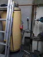
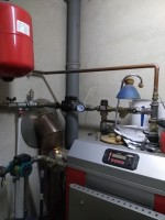
    Can you take pictures of the installation? Why don't you have a valve with an actuator?
  • #7 17112351
    przemas.j
    Level 10  
    Where to look for this capacitor? In this tin what the gear selector is like?
  • #8 17112359
    misiek1111
    Level 36  
    Maybe take some photos.
  • #9 17112389
    piracik
    VIP Meritorious for electroda.pl
    The capacitor is located in the pump box. Where gear changes :)

    In order to measure its capacity, it is absolutely necessary to turn off the voltage (by removing the plug from the socket).
    After waiting a while (
  • #10 17112392
    przemas.j
    Level 10  
    This installation was done by the company. They have been several times and they say it's ok. But it's not ok because all rotameters show nothing. And when I ask them about rotameters, they say that it can be so many times. But I know that it is okay. Yes, it can't be. Because I can't adjust the flow. And I would like to increase the flow in the rooms where I have panels. Also the company that made it washes my hands and I was left with a problem. I have three pumps, but two are in the hot water area. probably nothing common. The pump in what, if you set it to 3 gear, chases this water because the stove heats up to the set temperature for a very long time. And the temperature set on the stove is 55 °
  • #11 17112402
    piracik
    VIP Meritorious for electroda.pl
    Are the installation and the pump new?

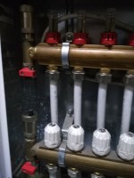
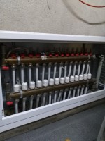
    Be sure to send a photo of the splitter.
  • #12 17112421
    przemas.j
    Level 10  
    Everything is new. Newly built house.
  • #13 17112423
    piracik
    VIP Meritorious for electroda.pl
    OKAY. Then we are waiting for the photos.
  • #15 17112464
    przemas.j
    Level 10  
    I did not design this installation. Everything was commissioned to the company. And why did they not decide on a valve with an actuator. I do not have a green idea. They said that with this 3-way valve it will go and there is a lime here? .
  • ADVERTISEMENT
  • #16 17112562
    tata1
    Level 20  
    It was similar with me, the rotameters were set to "0", I turned the knob on the three-way thermostatic valve and it started. I still do not know why it can work in various positions, and it does not work in other positions. Even millimeter differences in the valve knob and rotameters "stood up". Maybe you just need to find "the right position on the valve"

    My feeling is that if the floor heating was on a three-way mixing with an actuator (higher flow), and not thermostatic (lower flow), this would not be the case. I was about to rewrite it, but found "this item" and it stayed that way and it's OK.
  • #17 17112979
    lampa
    Level 19  
    maybe read this: Link
    good luck

    I corrected the broken link. MOD - piracik
  • #18 17113345
    gersik
    Level 33  
    It was not a "company" but bunglers. How they couldn't even turn the pump. This is not how it is supposed to be. By closing the system, you deprived your boiler warranty. installation around the boiler to be redone. You paid it, ask these gentlemen to work it out quickly. The cauldron with such a cold return will not last long, but until it is replaced with the 5th grade, it comes. There should be two three-way valves (one with an actuator) and two pumps and the third one for DHW.
  • #19 17113366
    przemas.j
    Level 10  
    Pump checked. Filters checked and then lame. Protameters are as if closed

    Added after 21 [minutes]:

    The company that did it, I have enough of it. It also stays with it.
  • #20 17113412
    gersik
    Level 33  
    And it will be a shame until the installation is redone. In addition to the things that I described above, I could use a buffer, then the installation would be without problems.
  • #21 17113415
    przemas.j
    Level 10  
    Today there was a new "specialist" with said that this three-way valve has a slow flow - what do you think about it because my hands are dropping.
  • #23 17113587
    piracik
    VIP Meritorious for electroda.pl
    A strange situation.

    If this pump would not be able to cope or the valve (which has a flow of 2.5 m3 at a resistance of 3 msw, and a maximum of 4.5 m3) would have too low flow,
    then after turning 6 - 8 loops, the rest should swing. Because for this it should be enough.

    I'm not saying that the pump and valve are in reserve, but in my opinion the problem lies elsewhere.

    The question is what is behind the boiler. This pipe from the bottom of the mixing valve where it goes and what is there.
    The question is whether if you turn the mixing valve to max or min, does something move (test on a cold boiler)
    The question is whether the rotameters have zero at the top and max at the bottom and are they always up or vice versa?

    The boiler room is not perfect, but it should work somehow. The flow, if not all loops, should be at least some.
  • #24 17113655
    przemas.j
    Level 10  
    There is a return from the bottom of the valve, it goes behind the stove and it is connected back to the installation. There is also a non-return valve on the return.

    Added after 58 [seconds]:

    I'm going to try to twist the loop. Let's see if anything moves.
  • ADVERTISEMENT
  • #25 17113665
    piracik
    VIP Meritorious for electroda.pl
    Take a picture, just a little more light.

    Have you checked if the check valves are in the right direction?
    The return from the underfloor heating system first returns to the mixing valve, and only then connects back to the installation and to the boiler?
  • #26 17114722
    1985matti
    Level 15  
    1. Copper installation with galvanized couplings is probably forbidden by the standard, or at least very unfavorable in installation.
    2. Check if the upper or lower beam is warmer, maybe directions are reversed and therefore the flow meters do not work.
    3. in the three-way valve we have a filter on the hot water side, but there is no on the cold return side - maybe there is some muck there and no inflow, maybe something fell and blocked the valve.
    4. Check that both beams are warm, they should have a comparable temperature.
    5. the valve on the hot utility water pump is installed in front of the pump, not what is an error.
    6. What's your temperature on the boiler?
    7. Turn on the pump from the floor heating and try to turn this knob from the mixing valve several times from 1 to 6 and check again if the pipe after the valve gets warm and cold.
    8. take a picture of what is behind the boiler, maybe someone has plugged the return from the floor heating to the return from the hot water.
    9. Open or closed installation? What is the pressure on the installation ???

    This installation is probably one of the first of this company and they are just learning :) just a pity at the cost and material of the client.
    Don't bodyguards install it sometimes ??? :)

    The pump and mixing valve for this installation are selected approx.

    Added after 8 [minutes]:

    Check all the pipes in front of the battens in the box to make sure that all of the two ends are warm. Check as far as possible from the slat.
  • #27 17115506
    przemas.j
    Level 10  
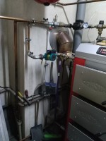
    Hello. This is what it looks like behind the stove. What the rest of it looks like on the stove at 55 °. The valve is set to 5.5, the maximum can be 6. Temperature immediately after the three-way valve measured with an electronic thermometer 38.5 °. Then temperature. On supply beam at beam start 37.1 at end of supply beam 36.2 ° on return beam at beam start 33.2 ° at beam end 31.8 °. 5 are also ok, that is, for the supply beam. As for the moment, the twist of the inflow to the beam is all rotameters for a moment of vibration. Yesterday I checked how to twist 7 circuits on the beam 7 out of 14, then the rotameters start to show something like 0.5 l
  • #28 17115507
    przemas.j
    Level 10  
    And yet. Closed installation. Pressure 1.5

    Added after 5 [minutes]:

    The valve as it turns from 0 to 6, the rora behind it gets warmer. Really something with this flow must be. Can disassemble this valve and something inside restricts this flow? Because why is there a difference in temperature even on the beam itself in relation to the beginning and end of the beam?

    Great snipe removed. Piracik mod
  • #29 19734181
    oscylot
    Level 11  
    I am not a specialist in this topic, but as far as I know, and I can be wrong, the water will activate the flow meter only in one direction, so maybe the water supply is not on this side of the beam.

Topic summary

The discussion revolves around a floor heating system in a 150 m² house experiencing zero flow on rotameters. The system includes a Solar 25-60/180 pump, a three-way valve (Vta 572-31700200), and a Brastal 25 kW charging furnace with 14 loops. Users suggest potential issues such as insufficient pump capacity, problems with the three-way valve, and the need for proper flow measurement. Recommendations include checking the pump's capacitor, ensuring correct installation of check valves, and verifying the flow direction. The author expresses frustration with the installation company, which has not resolved the issue despite multiple visits. Temperature readings indicate inadequate flow, prompting further investigation into the valve and system configuration.
Summary generated by the language model.
ADVERTISEMENT