logo elektroda
logo elektroda
X
logo elektroda

Poor Flow in Underfloor Heating System: Causes in New Construction with Air-Water Pump, 250m2 Area

marcel_76 52908 38
ADVERTISEMENT
Treść została przetłumaczona polish » english Zobacz oryginalną wersję tematu
  • #1 14392534
    marcel_76
    Level 13  
    Hello. In the newly built house, we have installed underfloor heating in its entirety, i.e. about 250m2. And so the bottom is served by one 7 circuit divider and the top two 4 and 6 circuit dividers.
    The entire heating system is based on a 16 pipe and a total length of approximately 1600m.
    The main power supply is an air-water pump which loads the 1000/200 multivalent tank (i.e. 800 liters of CO and 200 DHW) to about 43 degrees Celsius.
    In addition, a fireplace with a 24KW water jacket is connected to the container, used occasionally so far.
    The floor is powered from the upper part of the buffer through steel pipes (clamping system), the pump is controlled so that it does not pump the coolant cooler than 35 degrees into the floor.
    And so, start from the buffer pipe 1 inch, then the thermostatic mixing valve atm341 (protecting against loading too hot medium heated by the fireplace into the floor - the indicator is open to the maximum at 6)) then the pump Wilo Yanos pico 25 / 1-6- (ROW) and then ZZ, then parallel to all three dividers, i.e. one 7-point at the bottom and two 4-point and 6-point on the first floor daw at the top, separated by a tee for 3/4 pipes.

    At the moment, the heating is able to maintain the set temperature of about 21 degrees above, while the temperature at the bottom is much higher because the whole is lined with tiles, while the top heats up with more difficulty (most are panels but tiles also in the corridor, bathroom and utility rooms.)

    At the moment, the indicators on rotameters oscillate between 0-0.5 and not on all loops. When trying to regulate, i.e. checking the flow on individual beams, after tightening all loops and leaving one (each in turn) on the rotameter, the maximum flow of 2.5-3l / min is displayed. range, but it is known that the pressure in the water supply was greater)
    When two manifolds on the third are blocked, the rotameters show the flow in the limit of 1.5.
    There is no way I am now able to adjust the flow on the individual loops.
    The loops mostly consist of sections of 80 to 100 m, except for 4 shorter ones, between 30-50 meters.

    My question is whether the lack of flow is caused by the installation of only one circulation pump for such a large installation, or is it too weak.
    What solutions do you recommend?
    1.assembly of one more powerful pump - what kind?
    2. adding a second pump to supply the attic separately?
    3. ???????
  • ADVERTISEMENT
  • #2 14392566
    piracik
    VIP Meritorious for electroda.pl
    I understand correctly that you supplied two manifolds with one pump?
    What is the 30stka pump? Because not 25? How many meters of lifting?
    Do you have any schematic of this? Pictures? How do you regulate the temperature on the floor?
  • #3 14392585
    marcel_76
    Level 13  
    piracik wrote:
    I understand correctly that you supplied two manifolds with one pump?
    What is the 30stka pump? Because not 25? How many meters of lifting?
    Do you have any schematic of this? Pictures? How do you regulate the temperature on the floor?


    All three manifolds on one pump Wilo Yanos pico 25 / 1-6- (ROW) - the installer said that he would pull.
  • #4 14392601
    piracik
    VIP Meritorious for electroda.pl
    Recently, for less than 1000 meters, we chose the 25 / 1-8 pump and it can barely make it.
    Here, 25 can't do it. You have to choose something from 30 steak.

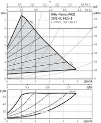
    I would not assume smaller than the WILO YONOS PICO 30 / 1-8.
  • #5 14392617
    marcel_76
    Level 13  
    piracik wrote:
    Recently, for less than 1000 meters, we chose the 25 / 1-8 pump and it can barely make it.
    Here, 25 can't do it. You have to choose something from 30 steak.


    And adding another one of the same type to the attic itself will do something?
  • #6 14392622
    piracik
    VIP Meritorious for electroda.pl
    Unless you give a second pipe from the boiler bypassing the pump to the ground floor.
    So that each pump draws from the boiler independently. (or there from the buffer, it doesn't matter).
    If you give a second pump after the first one, all the flow will go to the other pump.
    Additionally, check valves at the pumps.

    How many sections do you have? (loop)
  • #7 14392651
    marcel_76
    Level 13  
    piracik wrote:
    Unless you give a second pipe from the boiler bypassing the pump to the ground floor.
    So that each pump draws independently from the boiler. (or there from the buffer, it doesn't matter).
    If you give a second pump after the first one, all the flow will go to the other pump.
    Additionally, check valves at the pumps.


    I can branch the power supply behind the thermostatic valve and let the existing pump run separately upstream and the new pump downstream from the other. But is it enough?
  • #8 14392662
    krychu57
    Level 2  
    I am not a specialist, but I had the same problem with the floor heating - two levels, two manifolds and in winter on the higher level it was only 18 o C and at the bottom over 20 o C, the installation was powered by one pump. It turned out that there was air in part of the loop and the circulation pump was unable to do anything. I connected two hoses in turn to each loop and ran plumbing water. The air has been pushed out and now one circulation pump works, warm everywhere. The house has 200 m2.
  • ADVERTISEMENT
  • #9 14392676
    piracik
    VIP Meritorious for electroda.pl
    krychu57 wrote:
    I had the same problem with the two-level floorstand

    How many loops and how long, because the fact that 200m2 does not say much.

    Added after 1 [minutes]:

    marcel_76 wrote:
    supply after the thermostatic valve

    Did you really do it on a thermostatic rather than a motorized 3D?
    Enter how many of these sections you have.

    On the one hand, a Heat Pump (Mercedes), on the other, an old toddler (thermostatic valve)?
  • #10 14392687
    marcel_76
    Level 13  
    krychu57 wrote:
    I am not a specialist, but I had the same problem with the floor heating - two levels, two manifolds and in winter on the higher level it was only 18 o C and at the bottom over 20 o C, the installation was powered by one pump. It turned out that there was air in part of the loop and the circulation pump was unable to do anything. I connected two hoses in turn to each loop and ran plumbing water. The air has been pushed out and now one circulation pump works, warm everywhere. The house has 200 m2.


    And what kind of pump do you have, if you can ask, and what flows now?
    In addition, I have already vented the installation in this way, and as I write with the closures of 2 manifolds, alternatively one chula and the same way, when opening only one loop, the rotameter works, so there is probably no air anymore. In addition, everything is slowly warming up, but it is about that slowly. I believe that if I increased the flow it would heat up faster.

    Added after 3 [minutes]:

    piracik wrote:
    krychu57 wrote:
    I had the same problem with the two-level floorstand

    How many loops and how long, because the fact that 200 m2 does not say much.

    Added after 1 [minutes]:

    marcel_76 wrote:
    supply after the thermostatic valve

    Did you really do it on a thermostatic rather than a motorized 3D?
    Enter how many of these sections you have.

    On the one hand, a Heat Pump (Mercedes), on the other, an old toddler (thermostatic valve)?


    Thermostatic valve for protection against hot factor from the fireplace.

    sections as I wrote:
    bottom one beam 7 loops

    top 2 beams
    one 4 loops, including two short ones
    the second, 6 loops, including one short

    Added after 5 [minutes]:

    piracik wrote:
    krychu57 wrote:
    I had the same problem with the two-level floorstand

    How many loops and how long, because the fact that 200 m2 does not say much.

    Added after 1 [minutes]:

    marcel_76 wrote:
    supply after the thermostatic valve

    Did you really do it on a thermostatic rather than a motorized 3D?
    Enter how many of these sections you have.

    On the one hand, a Heat Pump (Mercedes), on the other, an old toddler (thermostatic valve)?


    This is what the installer suggested, but is this valve complicating anything? It is only supposed to protect against the power supply from the fireplace.
  • ADVERTISEMENT
  • #11 14392745
    krychu57
    Level 2  
    I have a pump, Type U 55-25 180, the plumber who later did something else for me, said that the trashy company of Wit, but he does not replace it as long as it works. I have 8 loops at the bottom and 6 at the top, what lengths I do not know. The house was built in 2008 and since then rotameters do not show reliable flows. In every place where there are tiles, and so I have in 80% of rooms, the floor is pleasantly summer. The heating is powered by an air-water heat pump.
  • #12 14392773
    piracik
    VIP Meritorious for electroda.pl
    krychu57 wrote:
    I have a pump, type U 55-25 180

    The question is, what kind of mixer do you have. Does it go directly from the pump?
    At friend's @ marcel_76 the thermostatic valve may cause (certainly causes) too high flow resistance. Unless the valve is 2 "in diameter, that's OK
    Still, the pump will be too small.
    So, to replace the pump and the type of mixer.
  • #13 14392806
    krychu57
    Level 2  
    The heat pump supplies a 500 l buffer tank and the underfloor installation is supplied by an electrically controlled three-way valve.
  • #14 14392819
    piracik
    VIP Meritorious for electroda.pl
    marcel_76 wrote:
    sections as I wrote:
    bottom one beam 7 loops

    top 2 beams
    one 4 loops, including two short ones
    the second, 6 loops, including one short


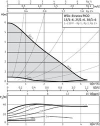
    So fast, you would need something about 4.5 meters of lifting with a capacity of 3.5 m3 / h
    The pump you have for this lifting height is just over 1m3 / h

    Added after 1 [minutes]:

    krychu57 wrote:
    the underfloor installation is powered by an electrically operated three-way valve

    Compared to thermostatic valves, these valves have practically no resistance.
  • #15 14392855
    marcel_76
    Level 13  
    piracik wrote:
    marcel_76 wrote:
    sections as I wrote:
    bottom one beam 7 loops

    top 2 beams
    one 4 loops, including two short ones
    the second, 6 loops, including one short


    So fast, you would need something about 4.5 meters of lifting with a capacity of 3.5 m3 / h
    The pump you have for this lifting height is just over 1m3 / h


    What pump and valve do you suggest?
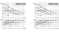
    What do you think of the SPRINTA 32/80 LFP?
  • #16 14392962
    piracik
    VIP Meritorious for electroda.pl
    The best Stratos Pico 25 / 1-8 Minus is the Plus price you stay with a diameter of 25

    Poor Flow in Underfloor Heating System: Causes in New Construction with Air-Water Pump, 250m2 Area
    Stratos 1-6 a bit too weak
    Poor Flow in Underfloor Heating System: Causes in New Construction with Air-Water Pump, 250m2 Area

    Poor Flow in Underfloor Heating System: Causes in New Construction with Air-Water Pump, 250m2 Area

    Additionally, check if the pump would be able to regulate the temperature to the floor. Alternatively, you can install a driver, eg ST 430 TECH
  • ADVERTISEMENT
  • #17 14393127
    marcel_76
    Level 13  
    piracik wrote:
    The best Stratos Pico 25 / 1-8 Minus is the Plus price you stay with a diameter of 25

    Poor Flow in Underfloor Heating System: Causes in New Construction with Air-Water Pump, 250m2 Area
    Stratos 1-6 a bit too weak
    Poor Flow in Underfloor Heating System: Causes in New Construction with Air-Water Pump, 250m2 Area

    Poor Flow in Underfloor Heating System: Causes in New Construction with Air-Water Pump, 250m2 Area

    Additionally, check if the pump would be able to regulate the temperature to the floor. Alternatively, you can install a driver, eg ST 430 TECH


    So disassemble the pump I have and install the one you recommend.
    CYou need to turn on this auxiliary pump to supply the attic.
    The current circulation pump is controlled from the controller which does not allow it to work with a power supply lower than 35 degrees, and moreover, in a row there is a room controller that turns it on when the temperature in the room drops (the controller is located in the attic in one of the cooler rooms), i.e. they must be met 2 conditions a drop in room temperature and an appropriate flow temperature
  • #18 14393202
    piracik
    VIP Meritorious for electroda.pl
    I would make the control dependent on the outside temperature.
    The driver that CI gave as an example is one of the cheapest. It has weather control with the function of a room regulator.
    If the room regulator signals that it is too warm, the controller will reduce the floor temperature by the programmed value, e.g. 5 * C
    This is a much better solution because you do not turn off the entire system, you do not cool down the floor, which will then start heating faster if the temperature in the room drops.

    35 * C? This is the top temperature for the floor. Why do you turn off the system then?
    I give 25-32 ° C to the floor at sources such as a pump or condensate and it is warm.
    The efficiency of the pump and the condensate decrease with increasing temperature. If, with the floor heating only, you heat with a pump above 40 * C all the time, you are wasting money in the drain.

    As for the push-up, you can try to give two. Of course, check valves on both.
    Think about changing the control to a more intelligent one, which will allow the pump to work in the most optimal parameters.
    Remember that the pump heats up to 50 * C, but at this temperature the ratio is 1: 1 where at say 30 * C it will be 1: 4
  • #19 14393294
    saskia
    Level 39  
    The first thing is 1600 meters. pipes on 17 loops are approx. 94 running meters for one loop.
    Way too much.
    I know from experience that 50 meters per loop is max. The more 50m is more asking for more trouble, respectively.
    The second problem is one pump for so many loops that are too long.
    With 2 or more manifolds, at least one of which has 6 or more loops, the system should be divided into the so-called zones-circuits with separate control, and set the boiler to heating on demand of any circuit.
    The basic benefits of this separation are the heating of the circuit that is required, and not the entire cycle, which results in considerable fuel savings and allows for different temperatures depending on the place of stay at the appropriate times of the day and night.
  • #20 14393348
    piracik
    VIP Meritorious for electroda.pl
    saskia wrote:
    The basic benefits of this separation are the heating of the circuit that is required, not the whole circuit, which results in considerable fuel savings

    Instantaneous heating requires increasing the temperature of the heat source.
    Increasing the temperature on the heat pump from 30 * C to 40 * C dramatically lowers its efficiency.
    It is cheaper to heat the whole house with low temperature all the time than to turn off, for example, the floor during the day to heat it back at night, which requires a higher supply temperature.
    And the topic of the weather returns to the floor, which for you is a fairy tale that has no economic justification. Greetings.
  • #21 14394386
    andrzej lukaszewicz
    Level 41  
    It is obligatory to add a separate pump to the upper distributors and to use the control with two regulators divided into two zones: bottom (ceramics) and top (panels). It would be optimal to use two mixing systems with a drive and different temperatures. mixing.
    Just like Kol. Piracik writes down below 30 degrees and let's say 35 upwards, so as not to lose the pump on the COP.
    Unfortunately, we do not know how the loops are made (for low-temperature heating, you should not give 3-layer pexes, only single-layer pipes, or preferably copper - unfortunately this price!) And if so, it is very dense every 10max 15cm.
    From what the author says, 1600 linear meters on 250 square meters is not very interesting, because it gives about 6.4 meters per 1 square meter of flooring with approaches, i.e. the pipes are actually placed every 20 cm, i.e. linden. This is how the minimum standard heating 35-45 degrees Celsius is done.
    The heat pump should be at least 7-8 meters per m2, and optimally 9-10, and thus more circuits. Normally (every 15 cm) it gives a maximum circumference of 10-12 m2, up to 14 m2 if it is, for example, a kitchen with cabinets under which it gives 1-2 pipes with a width of 60 cm, and the remaining floor is normal.
  • #22 14394486
    saskia
    Level 39  
    piracik wrote:
    saskia wrote:
    The basic benefits of this separation are the heating of the circuit that is required, not the whole circuit, which results in considerable fuel savings

    Instantaneous heating requires increasing the temperature of the heat source.
    Increasing the temperature on the heat pump from 30 * C to 40 * C dramatically lowers its efficiency.
    It is cheaper to heat the whole house with low temperature all the time than to turn off, for example, the floor during the day to heat it back at night, which requires a higher supply temperature.
    And the topic of the weather returns to the floor, which for you is a fairy tale that has no economic justification. Greetings.


    This is what is wrong.
    Continuous operation of the heat pump and continuous operation of the floor heating.
    Here I wonder why install a tank. :-)
    On the other hand, I did not write about the complete shutdown of any circulation for the night, etc., but about the heat demand to achieve the set temperature for a given circuit and then to maintain it.
    Why take heat from the tank to all circuits at the same time, if they never heat up to the same temperature at the same time.
    The one that has reached room temperature will switch off for an hour or a half and that's it. A heat pump with a buffer tank will be just a fish. :-)
    What people combine is like buying a fur discounted from 80,000 to 40,000 thinking that you made 40,000, and in fact 40,000 seemed unnecessarily. :-)
    If the PC runs non-stop, it will not only rain earlier, but also the exchanger will freeze (frost up), especially in winter. In addition, the costs of its continuous operation and circulation pumps. At some point, despite a good COP, PC will start to bring losses exceeding the savings from high COP.

    The PC needs some breaks at work, and so does the floor heating.
  • #23 14394595
    jack63
    Level 43  
    saskia wrote:
    The basic benefits of this separation are the heating of the circuit that is required, not the entire one, which results in considerable fuel savings and allows for different temperatures depending on the place of stay at the appropriate times of the day and night.
    - benefits (!) :D
    Everything is nice as an idea, but how to implement it? And it's not just about:
    piracik wrote:
    Instantaneous heating requires increasing the temperature of the heat source.
    What is the truth. However, the author of the topic has a lot of buffer.
    The biggest problem is managing this "mess" wisely. I do not expect that there will be a ready-made driver with an algorithm prepared for such a situation.
    Most controllers have simple or slightly modified PID algorithms, so customers are persuaded to heat at reduced power but almost all the time, and it is advisable not to exceed a 3 oC difference in temperature levels.
    Ideally, a single predictive ("predictive") controller covers the entire installation with several outputs. However, I am afraid that one has not yet been created in commercial form.
    A good "support" in this situation is weather control,
    piracik wrote:
    I would make the control dependent on the outside temperature.

    I support. In the absence of a predictive regulator, it is even an obligation.
    I suggest the author to get interested in a company that makes ventilation automatics and to submit a request for a quote for an "adult" driver with its installation and software.
    It may turn out that with such a large number of pumps, 3D valves, temperature sensors, etc., it will be cheaper to put it together in one controller with several inputs-outputs than buying, for example, separate controllers for each zone and each regulation.
    Not to mention the possibility of viewing and, if necessary, changing the settings via the Internet.
    piracik wrote:
    Remember that the pump heats up to 50 * C, but at this temperature the ratio is 1: 1 where at say 30 * C it will be 1: 4

    You came out of your backyard and start improvising. :cry:
    The COP of the air heat pump does not depend very much on whether the buffer temperature will be 35 or 50 (if it will achieve that much at all with an "economical" condenser exchanger), but above all on the temperature and ... humidity of the air flowing to the evaporator exchanger.
    Of course, the general rule, that is minimizing the difference in temperature between GZ and DZ, is correct, but for the AIR heat pump, the conditions around the DZ, that is the air-refrigerant exchanger, are "imposing", as well as its design and the method of fan and defrost control.
    I warn you against "secret" switching on the electric heaters in factory heat pumps in a situation where the cooling system does not work. Including the heaters lowers the COP to 1!
  • #24 14394991
    saskia
    Level 39  
    In order for the weather to do what you write about, it would have to be a mini meteorological station, temperature, pressure, wind force and its direction, precipitation, and it would be good to connect it to the Internet, to correct local data with local weather stations. :-) :-) :-)
    In addition, a small computer for data processing with the fastest possible processor (it could be connected to the buffer to improve COP) :-) a few peripheral drivers, sensors and some goodies would also fit for your well-being when paying your electricity bills. :-) :-) :-)
    Additional (questionable) savings can be obtained by paying bills directly from the account, the so-called direct debit. :-) We then have to work 24/7 so that there is always something on the account. :-)
    The sense of thermal comfort in the house is then puzzling, if we practically do not live there. :-)
  • #25 14395059
    jack63
    Level 43  
    saskia wrote:
    In order for the weather to do what you write about, it would have to be a mini meteorological station, temperature, pressure, wind force and its direction, precipitation, and it would be good to connect it to the Internet, to correct local data with local weather stations.

    You're exaggerating a little, but just a little. All this is achievable today. The problem with what money and what all the parameters are for.
    For you, any automation that does not contain 7 bimetallic thermostats is a whim and a difficult thing to imagine. :D
    It is not about the weather, but it is collecting all measurement data (input) and handling all elements that require constant change of settings (e.g. 3D valve actuators) (output) in one controller. The point is not to buy separate zone regulators or just floor distributors or heat pump start. There may be several of them in this installation, and they may cost more, and they will not have a "supervisor".
    With a professional controller with a good program, you can even "program" the dates of arrival of "aunt from America" to your Lady and set a different temperature.
    saskia wrote:
    The sense of thermal comfort in the house is then puzzling, if we practically do not live there.

    The concept of "we do not live" is quite relative for people who work long and hard. Why heat an empty house? It has to be warm when we come back to it.
  • #26 14395184
    saskia
    Level 39  
    Everything seems to be correct, everything can be done, the question is; why and whether it would make logical and economic sense.
    You can even have a "time zone" correction when your aunt and Hameryka come, so that she has daylight at midnight and she can swim in the pool, but the fact that she comes does not mean that everything around must be like in Hameryce. :-)
    You can even start working at convenient hours, but then you won't even earn the basic maintenance of such a house.

    I do not deny the use of a PC or floor heating, but everything must have some rational foundation.
    If you don't like what you like, you like what you have, and for many people the opposite is true. :-(
    Later they have a problem with either exploitation costs or fuel costs.
    Maybe it has little to do with CO, but once I had to do a similar research on my situation, namely the purchase of a heavy off-road vehicle that I needed (which does not mean necessary), after recalculation I bought it, but I bought a small car with it.
    Seemingly it was a bigger expense, but the right solution, a small car, due to its low fuel consumption, practically keeps it heavy.
    The cost of the second car and the cost of insurance have already been paid back after 3 months. because I did not have to use the heavy and voracious roadster every day and every time, which I have been using for over 8 years.
    The fact that something saves, for example, PC, does not mean that in order to save, we have to use it non-stop, because when we start to exceed the actual demand for thermal energy, even a PC with COP 10 does not make sense any longer.
    It's like with the fur purchase I wrote about.
    On the other hand, it does not make sense to buy a PC with an efficiency close to the house's demand, because not only will the pump run out quickly, but more often we will have a COP 1 or even lower.
    If we add a lot of unnecessary goodies to it, we have 2x higher costs than with simple heating el. excluding the depreciation of the investment. :-(
  • #27 14398076
    marcel_76
    Level 13  
    Hello. Thanks to everyone for the hints.
    I start with the simplest one, i.e. blasting the thermostatic valve, then I will check the flows on individual floors separately, i.e. up and down.
    If it would be enough, I will only buy the second, same pump for the second circulation, if not, I will use the suggestion of my colleague "piracik" and buy a Stratos Pico 25 / 1-8.

    If it is chulało, you will only install a three-way valve (to protect the floor when heating the fireplace) and that's it.

    I hope that the first option will work, i.e. the second pump, the same as I already have (but the stratos costs a bit).
    I still have a question because I have seen Wilo pumps with an LCD display somewhere, which supposedly adapt themselves to the floor heating, i.e. power depending on the temperature on the supply and return, etc.
    Maybe someone knows what model it is?
  • #28 14399917
    marcel_76
    Level 13  
    I removed the thermostatic valve and the flow with 3 manifolds turned on is in the range of 1-1.3. When closing the lower distributor, the upper one is in the range of 1.5-1.7 and it will not perform any more. But that's definitely better than below 0.6 before disassembling the valve. How do you think to buy a second wilo pico 25 / 1-6 and divide the ground floor from the attic into two pumps or the entire installation of wilo stratos 25 / 1-8 as suggested by one of your colleagues?
  • #29 14400422
    saskia
    Level 39  
    marcel_76 wrote:
    I removed the thermostatic valve and the flow with 3 manifolds turned on is in the range 1-1.3. When closing the lower distributor, the upper one is in the range of 1.5-1.7 and it will not perform any more. But that's definitely better than below 0.6 before disassembling the valve. How do you think to buy a second wilo pico 25 / 1-6 and divide the ground floor from the attic into two pumps or the entire installation of wilo stratos 25 / 1-8 as suggested by one of your colleagues?


    You already have all the information, the decision is up to you.
  • #30 14400459
    marcel_76
    Level 13  
    saskia wrote:
    marcel_76 wrote:
    I removed the thermostatic valve and the flow with 3 manifolds turned on is in the range 1-1.3. When closing the lower distributor, the upper one is in the range of 1.5-1.7 and it will not perform any more. But that's definitely better than below 0.6 before disassembling the valve. How do you think to buy a second wilo pico 25 / 1-6 and divide the ground floor from the attic into two pumps or the entire installation of wilo stratos 25 / 1-8 as suggested by one of your colleagues?


    You already have all the information, the decision is up to you.

    I will wait a little, see how it heats up, i.e. whether the floor heats up faster and more easily and I think that I will enter two circuits so as not to heat the bottom of the house if it is not necessary and vice versa.
    I think that you could buy a stratos 25 / 1-6 for power supply, because it is probably more efficient than the pico YANOS 25 / 1-6

Topic summary

The discussion revolves around issues related to poor flow in a newly constructed underfloor heating system covering 250m2, powered by an air-water heat pump. The system utilizes multiple manifolds and a single pump, which has raised concerns about insufficient heating, particularly on the upper floor. Participants suggest potential causes, including inadequate pump capacity, air trapped in the loops, and high flow resistance from the thermostatic mixing valve. Recommendations include venting the system, adding a second pump, and considering more efficient models like the Wilo Stratos Pico 25 / 1-8. The importance of proper loop lengths and zoning for better temperature control is emphasized, along with the need for a more sophisticated control system to optimize heating efficiency.
Summary generated by the language model.
ADVERTISEMENT