logo elektroda
logo elektroda
X
logo elektroda

Calculating Resistor Value for 9 White LEDs at 5V: Power Supply from Computer

bicik4096 7905 18
ADVERTISEMENT
Treść została przetłumaczona polish » english Zobacz oryginalną wersję tematu
  • #1 17227440
    bicik4096
    Level 4  
    Hello

    In the case of a single led diode, visit: http://kalkulator.majsterkowicza.pl/oblicz/rezystor_do_LED - you can choose a resistor for the voltage and led and after the trouble.

    In the case of one diode, I had no problem. When I was to connect 9 LEDs, at 5V from the computer's power supply, a problem appeared. I don't know what to use the resistor.

    The LED flashlight has 9 diodes which were powered by 3x1.5V = 4.5V with voltage. I have efficient 5V from the computer power supply.

    So how to calculate the value of the resistor so that the diodes last longer? Or maybe it's better to power them with a stabilizer - by setting yourself 4.5 V or less?
  • ADVERTISEMENT
  • #2 17227451
    Crazy
    Level 15  
    It depends how you want to connect these diodes :)

    If in parallel, the voltage on each will be 5 V and the current depending either on the resistor on each of the diodes or on the resistor just behind the power input (this is not done).

    If in series, you need to know the voltage drop across the diodes (probably something around 2.2V) and it turns out that this voltage will be too little for so many diodes.

    In my opinion, by connecting in parallel, add a separate resistor to each diode (due to the dissipated heat, i.e. 2.2V drop on the diode times 20mA, it gives you 44mW, if you gave one resistor, it would have to be at least 396mW and for thermal reasons and a series of 0.5W)

    As for its value, remember that the brightness of the diode is controlled by its current not greater than that specified in the catalog note (usually 20mA).

    greetings :)
  • ADVERTISEMENT
  • #3 17227456
    HD-VIDEO
    Level 43  
    bicik4096 wrote:
    the LEDs will last longer


    They should be connected each with a series resistor, then these series in parallel.
  • #4 17227462
    kacpo1
    Level 33  
    Crazy wrote:
    It depends how you want to connect these diodes

    Topic...
    Crazy wrote:
    resistor right after the power input (this is not done).

    Half-truths are all lies. This is not the case with LEDs of different colors.
    Crazy wrote:
    As for its value, remember that the brightness of the diode is controlled by its current not greater than that specified in the catalog note (usually 20mA).

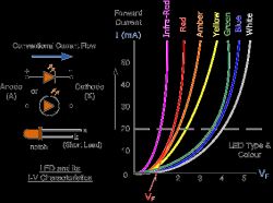
    And again ... You want to tell me that if I connect a 3V 10A power supply to the white diode, the diode will burn? No.
    The current flowing through the diode depends on the voltage across the diode.
    Calculating Resistor Value for 9 White LEDs at 5V: Power Supply from Computer
    As you can see in the picture, at 3V the diode will not conduct more than ~ 10mA
  • #5 17227468
    HD-VIDEO
    Level 43  
    And since the treatment LED lights are like light bulbs. How do you know what specific diodes have forward voltage?

    Do not write out stupid things yourself
  • #6 17227480
    Crazy
    Level 15  
    @ kacpo1 what's your power supply? 5V first thing
    Why not give a resistor right behind the power supply? :
    The first thing is temperature (believe it is lethal for more LEDs and I doubt that the author will be happy with a large resistor)
    The second thing is FAILURE: you burn one resistor, you will probably damage all the diodes (We do not teach bad manners from the beginning of learning for a few pennies (in production costs almost hundredths of a penny))
  • #7 17227497
    krzysiek_krm
    Level 40  
    kacpo1 wrote:
    Half-truths are all lies. This is not the case with LEDs of different colors.

    This is not done with none LEDs, even of the same color, due to the dispersion of characteristics.
    kacpo1 wrote:
    As you can see in the picture, at 3V the diode will not conduct more than ~ 10mA

    Give the bearings of the manufacturer that makes the diodes without any production spread .
    HD-VIDEO wrote:
    They should be connected each with a series resistor, then these series in parallel.

    It is the only possible way . However, some caution must be exercised, if the LEDs are white (they have a relatively large Vf) and have a relatively large Vf catalog spread, the nominal voltage across the resistor may be too low.
  • #8 17227498
    gumisie
    Level 43  
    bicik4096 wrote:
    When I was to connect 9 LEDs, at 5V from the computer's power supply, a problem appeared.
    What trouble, more details can you ask for?
    As long as you use a LED module and not individual LEDs with:
    bicik4096 wrote:
    The LED flashlight has 9 diodes which were powered by 3x1.5V = 4.5V with voltage
    No problem, each diode has its own resistor (connected in series) limiting its current.
    To lower the voltage from 5V (ATX) to 4.3V, insert a diode in series (e.g. 1N4002).
  • #9 17227506
    HD-VIDEO
    Level 43  
    gumisie wrote:
    The LED flashlight has 9 diodes which were powered by 3x1.5V = 4.5V with voltage
    No problem, each diode has its own resistor (connected in series) limiting its current.


    How do you know there are resistors there?

    I have to show a LED flashlight without resistors and powered by 3x1.5V
  • ADVERTISEMENT
  • #10 17227508
    gumisie
    Level 43  
    HD-VIDEO wrote:
    How do you know there are resistors there?
    Because:
    gumisie wrote:
    could you ask for more details?
  • #11 17227529
    HD-VIDEO
    Level 43  
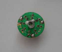
    Flashlight, 9 LEDs, 3x1.5V, size AAA.

    Calculating Resistor Value for 9 White LEDs at 5V: Power Supply from Computer Calculating Resistor Value for 9 White LEDs at 5V: Power Supply from Computer

    Where are the resistors?


    Review:
    Power supply set to 4.5V (no current limit), current consumption 650mA and increasing.

    You can see why this "LED flashlight" should be powered from ordinary zinc-carbon batteries and not from alkaline-manganese or rechargeable batteries.
  • #12 17227543
    gumisie
    Level 43  
    HD-VIDEO wrote:
    Where are the resistors?
    In your mute, but we know nothing what kind of flashlight the author of the topic has.
    Remember that AA "batteries", due to their own resistance, act as a power supply.
  • #13 17227558
    HD-VIDEO
    Level 43  
    If we do not know, I do not write what to do:

    gumisie wrote:
    bicik4096 wrote:
    The LED flashlight has 9 diodes which were powered by 3x1.5V = 4.5V with voltage
    No problem, each diode has its own resistor (connected in series) limiting its current .
    In order to lower the voltage from 5V (ATX) to 4.3V, insert a diode in series (e.g. 1N4002 ).


    Added after 6 [minutes]:

    And I put the 1N4004 diode in the flashlight shown above.

    Power supply 5V, current consumption 510mA (and increasing), voltage drop on the 1N4004 diode 730mV
  • #14 17227586
    gumisie
    Level 43  
    HD-VIDEO wrote:
    If we do not know, I do not write what to do:
    You are right, we also do not impose our own right on other users, nor do we edit someone else's statement.
    greetings
  • ADVERTISEMENT
  • #15 17227631
    HD-VIDEO
    Level 43  
    And what I edited; you told the user to connect the 1N4002 diode, you wrote that there are resistors there and you do not know if they are.

    The right thing is that the post about connecting the diode is harmful without knowing the structure of the flashlight.
  • #16 17228398
    gumisie
    Level 43  
    HD-VIDEO wrote:
    The right thing is that the post about connecting the diode is harmful
    Possible, but I wrote:
    gumisie wrote:
    To lower the voltage from 5V (ATX) to 4.3V, insert a diode in series (e.g. 1N4002).
    And no matter if it is: 1N4002, or 1N4004, but a "rectifying" silicon diode (0.7V) and minimum current (Io = 1A).
    Sorry, it's not my fault that:
    HD-VIDEO wrote:
    Power supply 5V, current consumption 510mA (and increasing), voltage drop on the 1N4004 diode 730mV
    Put in two diodes connected in series (2 x 0.7V = 1.4V).
    5V - 1.4V = 3.6V (unless the white LED "burns out") :D
    HD-VIDEO wrote:
    not knowing the structure of the flashlight.
    If I knew that you, know the structure of the flashlight that the author of the topic has, I would not write:
    gumisie wrote:
    What trouble? Can you ask for more details?
    ==================
    Forgive me, but this, your answer (# 3):
    HD-VIDEO wrote:
    They should be connected each with a series resistor, then these series in parallel.
    To the question (# 1) :!: :
    bicik4096 wrote:
    So how to calculate the value of the resistor so that the diodes last longer? Or maybe it's better to power them with a stabilizer - by setting yourself 4.5 V or less?
    I will leave without comment.
    greetings

    PS
    I give one hundred points to the person who gives specific data, "catalog" LEDs from this flashlight that the author of the topic has.
  • #17 17231134
    RebellionArts
    Level 23  
    Hello,

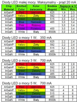
    What's all this for? Maybe graphs from an oscilloscope ???

    Simple google photo / graphic:
    Calculating Resistor Value for 9 White LEDs at 5V: Power Supply from Computer


    3 to find out what the diode is. Suppose low power.
    min. 3V, we have 5V.
    For 9, it is (9x5) 45V in series so that they all shine. (Current efficiency in this configuration can be max. 20mA)
    So we connect (because we only have 5V) in parallel, i.e. the same voltage and more current (compared to the serial one). The voltage must drop to 3V for each diode, so we calculate the resistance of the resistor for 2V (there will be a drop on it).
    R = U-Ud / Id
    R = 5V - 3V / 20mA
    R = 2V / 20mA
    R = 100 ohms.

    Such a resistor for each diode.
    And how does the parallel diagram look like on the Internet.
    The diode polarization diagram is also available on the Internet.
    And on the electrode heaps of topics about LEDs.
    Embarrassment.
  • Helpful post
    #18 17231322
    398216 Usunięty
    Level 43  
    Diodes in such a flashlight as shown by a colleague HD-VIDEO, as well as many other similar in terms of price, do not have any resistors. They are connected in parallel, as a result of which after a few or several hours on good batteries (not at all alkaline), first the one with the lowest voltage falls, then the next one and the next - the only current limiter is the internal resistance of the battery. Sometimes the resistor is additionally "made" by a pressure spring - made of a resistance wire.
    Even LEDs of the same color and from the same production series can have different forward voltages - sometimes even 300mV and in the case of LEDs it is a lot - just look at the current characteristics that Kol.kacpo1 has included. It cannot be said that each white LED has the same forward voltage - there are also deviations and you can even find white LEDs with a forward voltage (declared by the manufacturer) over 3.5V and 3V.
    gumisie wrote:
    I give one hundred points to the person who gives specific data, "catalog" LEDs from the flashlight he has (ł)
    You can already admit that to yourself. Since you say there are LEDs with resistors ....
    gumisie wrote:
    No problem, each diode has its own resistor (connected in series) limiting its current
    (I did not edit anything that would not be a grudge).

    And by the way - my colleague, as I can see from the posts you write - of those who are looking for a hole in the whole, and then (if there is no one) they drill down the topic until everyone finally forgets what it was about, or change, under the influence statements, subject.
    What is the benefit of such a discussion?
    Studded posts? *
    Sowing confusion? *
    Showing how wise I am? *
    Improving your self-esteem? *
    An interesting way to camouflage your own mistakes.

    To the author of the topic - you got the answer in post # 2 and confirmation in # 3.
    The rest of the topic is an attempt to eliminate / explain / rectify the erroneous assumptions of colleagues who then began to speak out.

    * Delete as appropriate.
  • #19 17231391
    retrofood
    VIP Meritorious for electroda.pl
    398216 Usunięty wrote:

    To the author of the topic - you got the answer in post # 2 and confirmation in # 3.
    The rest of the topic is an attempt to eliminate / explain / rectify the erroneous assumptions of colleagues who then began to speak out.

    And enough.

Topic summary

The discussion revolves around calculating the appropriate resistor value for connecting nine white LEDs to a 5V power supply from a computer. Users suggest connecting the LEDs in parallel, each with its own series resistor to limit current and prevent overheating. The voltage drop across each LED is typically around 2.2V, necessitating a resistor to manage the excess voltage. Calculations indicate that for a 5V supply and a desired current of 20mA per LED, a resistor value of 100 ohms is appropriate. Concerns are raised about the variability in forward voltage among LEDs, which can lead to uneven brightness and potential damage if not properly managed. The use of a diode (e.g., 1N4002 or 1N4004) in series to drop voltage is also discussed as a method to protect the LEDs.
Summary generated by the language model.
ADVERTISEMENT