logo elektroda
logo elektroda
X
logo elektroda

Transition from TN-C to TN-CS - the chapter point, and some novice questions

elektryk-uczen 34818 10
ADVERTISEMENT
Treść została przetłumaczona polish » english Zobacz oryginalną wersję tematu
  • #1 17769545
    elektryk-uczen
    Level 6  
    Hi,

    I note right away that I am still learning, so please be understanding. The questions are as follows:

    1) How best to perform the PEN to PE and N split point in a TN-C installation. I've seen 3 "schools" in general, all of them lead to the same but different way of connection:

    A) On the RCD terminal, I understand that it only makes sense in the case of small switchgears / short cables, when the cables from the meter to the switchgear are not replaced, and it makes sense with a maximum of 1 RCD.
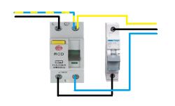
    Transition from TN-C to TN-CS - the chapter point, and some novice questions

    B) On the PE bridge, this seems to make the most sense with small substations.
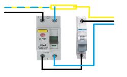
    Transition from TN-C to TN-CS - the chapter point, and some novice questions

    C) The division into a separate bridge N1 and N2, it probably only makes sense with larger switchgears and a few RCDs, because most of the "home" ones have only 2 bridges for PE and N installed at the factory.
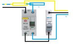
    Transition from TN-C to TN-CS - the chapter point, and some novice questions

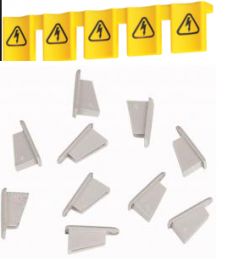
    2) As you deal with too long jumper rails, it seems most sensible to pull the copper out of the plastic sheath, break the tooth under the N in the RCD, cut the copper after the last tooth connected, cut the plastic a little further so that it is not possible to touch the live metal and put it back on .

    3) What is the best option for joining aluminum with copper (for cases A, B, C) because it often happens that someone has aluminum meter wires, which for some reason cannot / will not be replaced.
  • ADVERTISEMENT
  • Helpful post
    #2 17770176
    Brivido

    Level 34  
    B / C is a good choice depending on the size, but rather B.
    2. It is ok. There are also plugs for the ends of the rails, they will not hurt, or wrapping the rail with tape, although it is a bit of "wireworm"
    3. You simply attach an aluminum wire to such a brass strip, and screw a copper wire to the other connectors.
  • #3 17770288
    elektryk-uczen
    Level 6  
    Brivido wrote:
    A good choice is B / C depending on the size, but rather B.


    What about solution A what is worse than the others (except that the others are more orderly)?

    Brivido wrote:
    A good choice is B / C depending on the size, but rather B.
    2. It's ok. There are also plugs for the ends of the rails, they will not hurt, or wrapping the rail with tape, although it is a bit "wireworm


    I can see there are even two kinds of top and side attaching, thanks :) :

    Transition from TN-C to TN-CS - the chapter point, and some novice questions

    Brivido wrote:
    3. You simply attach an aluminum wire to such a brass strip, and screw a copper wire to the other connectors.


    And what if I do not have enough cable (because, for example, the switchgear has bridges at the bottom and the cable comes from the top) and solution A is left? How to extend such a cable in a switching station according to the art, let's make it harder to use aluminum.
  • ADVERTISEMENT
  • Helpful post
    #4 17770359
    Shadowix
    Level 31  
    Rule of thumb: one clamp - one wire. This tidies up the cables, removes weaknesses and speeds up your work. As for the comb rail for connecting devices, I recommend the apparatus with the N track on the left side. And of course, dedicated plugs. As for joining aluminum with copper, there were already a few topics, as well as cable extension. In the vast majority of switchboards, "bridges" can be installed either at the top or at the bottom. Or you can always give a TH35 rail mount ...
  • #5 17770936
    kkas12
    Level 43  
    elektryk-uczen wrote:
    A) On the RCD terminal, I understand that it only makes sense for small switchgears ...
    No buddy, it makes no sense or justification.
    And it's not a school.
    Sorry, but this is a manufactory run by a bungler.
  • #6 17770950
    Anonymous
    Level 1  
  • ADVERTISEMENT
  • #7 17771972
    elektryk-uczen
    Level 6  
    kkas12 wrote:
    elektryk-uczen wrote:
    A) On the RCD terminal, I understand that it only makes sense for small switchgears ...
    No buddy, it makes no sense or justification.
    And it's not a school.
    Sorry, but this is a manufactory run by a bungler.


    Can you buddy explain to me why? I mean specific reasons and not a "bungler-run manufacture", by no means I stick to this method, but I want to understand why it is wrong.
  • ADVERTISEMENT
  • Helpful post
    #8 17771988
    mawerix123
    Level 39  
    elektryk-uczen wrote:
    Can you buddy explain to me why?


    Because you should avoid such connections, the more so if different cross-sections of wires are mounted to the terminal of the apparatus ...
    It is unacceptable in the case of the PEN conductor, a poor contact in this terminal may cause a dangerous voltage on the enclosures of the receivers in protection class I.

    To connect only the strips and each wire in a separate clamp.
  • #9 17772027
    elektryk-uczen
    Level 6  
    mawerix123 wrote:
    elektryk-uczen wrote:
    Can you buddy explain to me why?

    Poor contact in this terminal may cause a dangerous voltage on the enclosures of receivers with protection class I.


    In the event of a phase breakdown on this housing, because there will be no connection to the PEN, it will be still under voltage, because in the absence of a breakdown, at most this device will not work properly - right, is it correct?

    In any case, the question of the incorrectness of such a connection is already clear to me - several wires in one terminal should not be used due to the fact that it does not guarantee a secure contact, which may result in the paragraph above.

    Can someone give an example of such a connector for the th35 bus that should be used to connect in this case - at the top, the input, at the bottom, the output, e.g.

    I thank my colleagues for their help.
  • Helpful post
    #10 17772054
    mawerix123
    Level 39  
    elektryk-uczen wrote:
    In the event of a phase breakdown on this housing, because there will be no connection to the PEN, it will still be under voltage, because if there is no breakdown, at most this device will not work properly - right, is it correct?


    I do not understand this sentence, it is not about the breakdown of the device and the voltage that appears on the PE conductor at every point of the installation after the PEN break, the break in the PEN terminal will cause the voltage to close through any load and return to the RCD through the blue conductor and then to the PE conductor .

    elektryk-uczen wrote:
    Can someone give an example of such a connector for the th35 bus that should be used to connect in this case - at the top, the input, at the bottom, the output, e.g.


    What you mean is ZUG -> https://www.google.com/search?q=zug+th35&sour...57XgAhWntYsKHf_SCwYQ_AUIDigB&biw=1366&bih=666

    You can also use a strip -> http://stan-met.pl/oferta/listwy-zaciskowe-ni-pe/th-35-7/
  • #11 17772096
    elektryk-uczen
    Level 6  
    mawerix123 wrote:
    elektryk-uczen wrote:
    In the event of a phase breakdown on this housing, because there will be no connection to the PEN, it will still be under voltage, because if there is no breakdown, at most this device will not work properly - right, is it correct?


    I do not understand this sentence, it is not about the breakdown of the device and the voltage that appears on the PE conductor at every point of the installation after the PEN break, the break in the PEN terminal will cause the voltage to close through any load and return to the RCD through the blue conductor and then to the PE conductor .

    elektryk-uczen wrote:
    Can someone give an example of such a connector for the th35 bus that should be used to connect in this case - at the top, the input, at the bottom, the output, e.g.


    What you mean is ZUG -> https://www.google.com/search?q=zug+th35&sour...57XgAhWntYsKHf_SCwYQ_AUIDigB&biw=1366&bih=666

    You can also use a strip -> http://stan-met.pl/oferta/listwy-zaciskowe-ni-pe/th-35-7/


    Everything is clear, thanks for your help.

Topic summary

The discussion revolves around the transition from TN-C to TN-CS electrical systems, specifically focusing on the optimal methods for splitting the PEN conductor into PE and N in various switchgear configurations. Three main approaches are debated: A) connecting at the RCD terminal, which is suitable for small installations; B) using a PE bridge, preferred for small substations; and C) creating separate bridges for N1 and N2, which is more applicable for larger switchgears. Participants emphasize the importance of secure connections, advising against multiple wires in a single terminal to prevent dangerous voltage issues. Recommendations include using dedicated plugs and ensuring proper cable management with TH35 rail mounts.
Summary generated by the language model.
ADVERTISEMENT