logo elektroda
logo elektroda
X
logo elektroda

Installation diagram TN C on TN CS, surge arrester, residual current device

ferguson123456 107887 36
ADVERTISEMENT
Treść została przetłumaczona polish » english Zobacz oryginalną wersję tematu
  • #1 10930058
    ferguson123456
    Level 10  
    Hello,
    I assume a post that friendly forum users will check the installation diagram for me. The installation in a residential house will be modernized and the measuring system will be sent to the outer wall and the main switchboard will be inside the building. The conversion protection is imposed by the Power Plant. I want to change the type of network to use a residual current device. One and only one, I am aware of the inconvenience this may entail. There is also a farm building with a four-wire and two-wire installation, so TN C must stay there.

    Of course, I checked the type of network and the measuring system is transferred by a licensed electrician.

    I am asking for constructive statements, as always, from competent people, so as not to unnecessarily prolong the post.

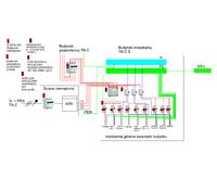
    https://obrazki.elektroda.pl/4609804600_1337868215.jpg


    Installation diagram TN C on TN CS, surge arrester, residual current device
  • ADVERTISEMENT
  • #2 10930214
    Miniax
    Electrician specialist
    PE enters on the RCD and N: o comes out
    Why do you want to N disconnect at the disc?
  • Helpful post
    #3 10930247
    mrst
    Level 18  
    Eliminate this bridge between the N and PE busbars. In addition, introduce the PEN directly to the PE strip and from there to the output of the limiter.
  • ADVERTISEMENT
  • #4 10930443
    0ceanborn
    Level 25  
    A terribly confused and unreadable drawing.

    Besides what mrst wrote, basically everything is fine.
    The induction switch does not have to be 4-pole, but the surge arrester is as good as it is.
    Quote:
    There is also a farm building with a four-wire and two-wire system, so TN C must stay there

    As for the outbuilding, it would be best to do a new TT or TN-S installation.
    Provide grounding and equipotential bonding.
    Then, however, the power must be released through the differential.
    I do not know what the installation looks like there, but in such buildings it is often done in trays, which makes it easier to replace the cables.
    Even if it is necessary to carve it into the wall or make a new one in the channels, the aesthetic considerations are probably not of great importance in the utility room.
    This is where the difference can be important.
  • #5 10930977
    ferguson123456
    Level 10  
    I missed this bridge because my concept changed while drawing the diagram. Thanks.
    Due to the fact that I wanted to show the wiring in more detail, the diagram did not come out as clearly as I wanted.
    I still have a question and doubt about the advice with connecting a surge arrester
    Quote:
    In addition, introduce the PEN directly to the PE strip and from there to the output of the limiter.

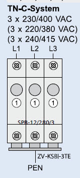
    If I want to include it in the system in a place where the network is of the TN C type, is it not properly connected? Photo below to support my way. Anyway, if you wanted to connect it in a TN CS system, you would have to use a 4-pole one

    Installation diagram TN C on TN CS, surge arrester, residual current device

    https://obrazki.elektroda.pl/3104982000_1337883029.jpg
  • #6 10930989
    michalekk1
    Level 24  
    ferguson123456 wrote:
    Anyway, if you wanted to connect it in a TN CS system, you would have to use a 4-pole one

    The question is, why do you want to protect the metallic wire connected to the same to what the overvoltage is "short-circuited"? :>
  • #7 10931064
    Anonymous
    Anonymous  
  • #8 10931308
    ferguson123456
    Level 10  
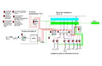
    Good The RDC is not connected properly. As for the quantity, I know but I do not change. RCD should be connected after PEN is divided into PE and N. I corrected the diagram, is it okay?

    https://obrazki.elektroda.pl/8550519000_1337888255.jpg

    Installation diagram TN C on TN CS, surge arrester, residual current device

    Yes, I didn't read with the album. The website says that it needs a voltage of 400 V, but 2 phases are enough - user manual.
    Bronek22 wrote:
    And where is GSU - unnecessary? Someone has to professionally redesign the switchgear - yes from scratch.
    For a large facility, a project made by a licensed person would be useful.


    And what will be included in the CSO, what will be connected to it? How do you know what the installations are made of and what are they in the building?
    This is the best way to rent a company and you will pay for it. Why would I assume a post as a panacea for everything is hiring a person with permissions. The forum would not exist and the facility is not big.
  • ADVERTISEMENT
  • #9 10931337
    Łukasz-O
    Admin of electroenergetics
    Yes, but the forum is for electricians, buddy, not people without or with poor knowledge. Therefore, please do not be surprised by such a reaction.
  • #10 10931369
    Paweł0381
    User under supervision
    ferguson123456 wrote:
    And what will be included in the CSO, what will be connected to it? How do you know what the installations are made of and what they are in the building?


    And your colleague knows what GSU is and what tasks it is supposed to fulfill?

    ferguson123456 wrote:
    Why would I assume a post as a panacea for everything is hiring a person with permissions.


    And if a colleague wants to do it without the help of at least a licensed person.
    Because ZE will chase a colleague for the scheme itself, without talking about the lack of permissions, What is the construction law in Poland for?
    My friend knows that everything is fine until something bad happens. What will the colleague support in court with "advice from the Forum"?
    And through the forum, a colleague will not perform the installation or project without permission and knowledge. Mr. Google is not knowledge but opinions of many people.
  • #11 10931434
    ferguson123456
    Level 10  
    I will not enter into sterile discussions with the Omniscient. It's easy to find logical errors in your arguments, e.g.
    Łukasz-O wrote:
    Yes, but the forum is for electricians, buddy, not people without or with poor knowledge. Therefore, please do not be surprised by such a reaction.


    Who are these electricians who must use the forum? This is not a place for specialists to gain knowledge. I will not write more.

    Paweł0381 wrote:
    And if a colleague wants to do it without the help of at least a licensed person.

    After all, I wrote that the measuring system is transferred by a person with permissions, otherwise the Power Plant will not receive it. I will have the opportunity to talk to a specialist but sooner but I prefer to get advice from several sources.

    I repeat the question about the correctness of the schema.
  • #12 10931495
    Łukasz-O
    Admin of electroenergetics
    ferguson123456 wrote:


    Who are these electricians who must use the forum? This is not a place for specialists to learn knowledge. I will not write more.


    A typical layman's approach. Electricity is a very extensive field. You think it's just knowing how to connect the "contact". Little knowledge little problem, big knowledge, answer yourself ... This is the case in every field, buddy.
  • #13 10931500
    Akrzy74
    Rest in Peace
    ferguson123456 wrote:

    I repeat the question about the correctness of the schema.

    This is not a pattern - this is the first thing. Second - when it comes to correctness, it is the lack of it.
  • #14 10931544
    Miniax
    Electrician specialist
    My friend, author, you complain that there is no help, that the adversaries are of a low level, and you cannot even answer the question I asked in the first post. You use cameras and connections, but you don't really know what purpose it is supposed to serve.
    3-phase RCD for single-phase circuits?
    Disconnecting N on the board?

    It's okay, but justify why this way. Here, unfortunately, circuit theory bows.
  • #15 10931573
    elpapiotr
    Electrician specialist
    Or maybe some more helpful justification why the cameras are powered from above, sometimes from below?
  • #16 10931724
    ferguson123456
    Level 10  
    Akrzy74 wrote:
    This is not a pattern - this is the first thing

    I wrote back but the censorship worked.

    ele_pp wrote:
    why the cameras are powered once from above, once from below?

    To make the diagram clearer.

    Miniax wrote:
    adversaries are of low level

    Where did I write that?

    Miniax wrote:
    3-phase RCD for single-phase circuits?

    I used 3 phase because I thought the induction was powered from 3 phases.

    Miniax wrote:
    Disconnecting N on the Board?

    Forum information:
    "A 3-pole switch is used in a TN-C, TN-CS network on a 4-0 wire section of the network, a 4-0 pole switch is used in a TN-S, TN-CS network (5-0 wire section of a network), TT, IT. In these networks there can also be a 3-pole switch, if there is no N conductor (e.g. machine with terminals: L1, L2, L3, PE)

    After the differential switch, we put 4-0 pole switches - N connection with PE causes the differential switch to trip. "
  • #17 10931755
    elpapiotr
    Electrician specialist
    Hello.

    But we do not use 4-way switch disconnectors. It's such a professional bias.

    The information from the forum is not always reliable and justified - after all, various people write, not always electricians.
  • #18 10931776
    ferguson123456
    Level 10  
    I will correct the diagram in line with Miniax's comments
  • #19 10931788
    Łukasz-O
    Admin of electroenergetics
    ferguson123456 wrote:

    Forum information:
    "A 3-pole switch is used in a TN-C, TN-CS network on a 4-0 wire section of the network, a 4-0 pole switch is used in a TN-S, TN-CS network (5-0 wire section of a network), TT, IT. In these networks there can also be a 3-pole switch, if there is no N conductor (e.g. machine with terminals: L1, L2, L3, PE)

    After the differential switch, we put 4-0 pole switches - N connection with PE causes the differential switch to trip. "


    This is a load of rubbish. Please provide a link to this work.
  • #20 10932156
    Anonymous
    Anonymous  
  • #22 10932954
    Łukasz-O
    Admin of electroenergetics
    ferguson123456 wrote:

    I thought you were here with us :D It is strange that no one reacted and wrote about the risk of unnecessary disconnection of the N track in three-phase circuits.

    And I do not see a grounded GSU in the diagram. Shockingly few districts for a single-family house - these are the 70s?
    Oven, dishwasher, washing machine, gn. in the kitchen. We already have 4 :) And where else are the rooms, lighting and other ...
  • ADVERTISEMENT
  • #23 10933053
    ferguson123456
    Level 10  
    Łukasz-O wrote:
    it's the 70's?

    Yes, there are currently two circuits for the whole house of aluminum wires and it has been in operation for 40 years. I did not increase the number of circuits after removing the induction hob. My main goal is to check the correct connection of the switching station. Increasing the number of circuits is not a problem later.
  • #24 10933123
    Łukasz-O
    Admin of electroenergetics
    First, write what these switches are for. Again, the unprofessional approach to electrical issues bows. The switchgear connection itself is not enough. Since you make installations, it should be made according to the standards and art of installation, not the way you think, because it works. Do not expect us to approve your ideas.
  • #25 10937243
    ferguson123456
    Level 10  
    I found some time, the diagram is finished, what do forum users think about it?

    Installation diagram TN C on TN CS, surge arrester, residual current device
  • #26 10937259
    elpapiotr
    Electrician specialist
    They think these 8A circuit breakers will be hard to find.
  • #27 10937298
    ferguson123456
    Level 10  
    Yes, my mistake is 6A. But now, after thinking about it, I think the induction is wrongly wired. However, I should have given a separate 3f RCD and 3f 20A miniature circuit breaker for induction and oven. What do you think?
  • #28 10937421
    Gregory_bg
    Level 26  
    You don't have to for permanently installed devices.
  • #29 10938611
    ferguson123456
    Level 10  
    I want to use RCDs on all circuits, please check the diagram
    Installation diagram TN C on TN CS, surge arrester, residual current device
  • #30 10938912
    mrst
    Level 18  
    The main switch in the switching station is still missing. You have socket and lighting circuits on one circuit, so when there is leakage in any of the sockets, you will not have lighting either

Topic summary

The discussion revolves around the installation diagram for a TN-C network with a focus on integrating a residual current device (RCD) and surge arrester in a residential setting. The user seeks advice on modifying their electrical system, which includes a farm building with existing TN-C wiring. Key points include the need to eliminate the bridge between the neutral (N) and protective earth (PE) busbars, proper connection of the surge arrester, and the importance of grounding and equipotential bonding. Various responses highlight the necessity of adhering to electrical standards, the potential risks of improper connections, and suggestions for circuit protection, including the use of appropriate circuit breakers for different appliances. The user is encouraged to consult licensed professionals for the installation and to ensure compliance with local regulations.
Summary generated by the language model.
ADVERTISEMENT