logo elektroda
logo elektroda
X
logo elektroda

Cable length and cross-section as well as selection of the inverter

sethir 54294 16
ADVERTISEMENT
Treść została przetłumaczona polish » english Zobacz oryginalną wersję tematu
  • #1 18070853
    sethir
    Level 13  
    Hello,

    Conditions:
    - 30 meters from the table to the inverter - it will be routed in the ground, I want to put it in a 75mm corrugated pipe so that in the future, when expanding, I can pull an additional pair of cables.
    - 4mm? cable on modules - 16 modules contain a total of 38.4 meters of cable (2 × 1.2m per module according to the specification for the LR6-60HPH-315M module was supposed to be 2 × 0.3m)
    - 22 meters extra cable for leveling loops on the table etc.

    The above gives a total of 90.4 meters of solar cable, does it make sense to run the cable from the table to the inverter with a cross-section of 6mm? if the modules are connected with a 4mm? cable.

    A single-phase inverter will have 4.6 kW, which gives 20A (ENERGA should accept such inverters until October 14, 2019), the length of connection to the main switchboard is 20 meters. Is a wire with a cross-section of 4 mm2 (YDY 5 × 4 mm? sufficient) sufficient ;) or maybe 6 mm? ultimately from this line will also power the PHEV car charger.

    Is it better to use a 3.68 kW inverter with a generator power of 5040 W (16x315W) (oversizing approximately 33% and it will be easier to modernize the installation after October 15, 2019), or install 4.6 kW (oversizing approximately 6.5%)

    Thank you for the advice and best regards
  • ADVERTISEMENT
  • #2 18071483
    ACCel
    Level 22  
    Want to bury your solar cable?

    After all, the most sensible is the aluminum YAKY 4 × 16mm?, even for DC. Unless you are over 600V.
    An earth cable in the ground (without a conduit) has better conditions than in a conduit. Of course, you can bury the Pechel just in case.

    On the AC side, the same aluminum YAKY 5 × 16mm?.
  • ADVERTISEMENT
  • #3 18073451
    sethir
    Level 13  
    Well, taking into account the Open Circuit Voltage = 40.6 V at STC conditions for 16 modules, I will have 649.6 V and the logic dictates that it should always be selected for the maximum possible conditions that arise. For NOCT at OCV I will have 606.40 V in the installation, and for maximum power from 497 to 539 V for STC, NOCT, respectively.
  • #4 18073586
    3301
    Level 34  
    sethir wrote:
    Well, taking into account the Open Circuit Voltage = 40.6 V at STC conditions for 16 modules, I will have 649.6 V and the logic dictates that it should always be selected for the maximum possible conditions that arise. For NOCT at OCV I will have 606.40 V in the installation, and for maximum power from 497 to 539 V for STC, NOCT, respectively.


    You should also take into account the temperature coefficient (read from the catalog card) and count for the temperature of minus 25 degrees Celsius.
    for example for LR6-310 the coefficient equals (-0.286)
    and then at Uoc (-25) it will be 46V which at 16 mod. da 736V

    Added after 6 [minutes]:

    The inverter should be placed as close to the panels and the power supply as possible. AC lead.
  • #5 18074019
    sethir
    Level 13  
    The fact, taking into account the temperature correction, these 736 can appear if it lights up well at -25C.

    The cable in this case at 50 meters is YKY 5 × 10mm? so that the drop is ~ 0.8%, or let go 20 meters to the place where the 5 × 10mm? inverter was planned and to the table of 30 meters 5 × 6mm?.

    How is the inverter secured against theft, e.g. by Fronius?
    I have a fenced area, the installation site will be monitored, but it can be different and I would not like to see an empty base in the morning.
  • ADVERTISEMENT
  • #6 18074192
    ACCel
    Level 22  
    Copper YKY is several times more expensive than the aluminum YAKY 16mm?. Why overpay?

    You can try to secure the inverter with shear nuts.
  • ADVERTISEMENT
  • #7 18074532
    3301
    Level 34  
    sethir wrote:
    The fact, taking into account the temperature correction, these 736 can appear if it lights up well at -25C.

    The cable in this case at 50 meters is YKY 5x10mm? so that the drop is less ~ 0.8%, or let go 20 meters to the place where the 5 × 10mm? inverter was planned and to the table of 30 meters 5 × 6mm?.

    How is the inverter secured against theft, e.g. by Fronius?
    I have a fenced area, the installation site will be monitored, but it can be different and I would not like to see an empty base in the morning.


    At 20A, 50m, and a Cu conductor of 10mm?, the drop will be more than 1.2% as you want Mon. 1% is a Cu 16 wire.
  • #8 18079542
    sethir
    Level 13  
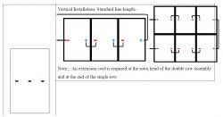
    Generally, you should not create loops and some manufacturers recommend that you lay DC cables in their module installation instructions so that you do not create these induction loops. However, in the case of Longi Solar LR6-60HPH, I see in the manual that the recommended module connection creates a clear loop. This is how it is with these loops. Below is an excerpt about connections.

    Cable length and cross-section as well as selection of the inverter

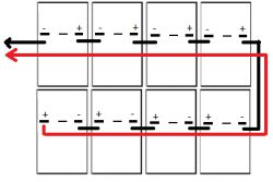
    Originally, I planned to pull the DC cables like this:
    Cable length and cross-section as well as selection of the inverter

    And now, when I read the module manual, I don't know whether or not to eliminate this loop.

    However, I will go in the direction of: 30 m AROT 50mm + DC cables 4mm or 6mm2 (I wonder here again) and from the inverter to the 27m YDYp 5x10mm? switchgear. For 4.6 kW I have a decrease of 0.84% and for 3.68 kW 0.67%. I cling to these drops because I read somewhere that it should not be higher than 0.8%.

    I have to put a hoop in the 80 cm trench. Will this order of layering be OK: 10 cm of sand, 120mm? hoop, 10cm of sand, AROT with DC cables, 10 cm of soil, blue foil and earth?

    Are there to be two overvoltage limiters for installation on the ground with a length of 30m of DC cable from the table to the inverter? DEHN clearly indicates that if L> 10m then yes. The question arises from the information obtained from one of the installers that if the DC installation is not carried out in the building, it does not have to be two.
  • #9 18079589
    ACCel
    Level 22  
    4mm or 6mm is just a matter of voltage drop.

    YDYp are you sure? This is the wire in. Did you mean YKY?
    If you like to pay for 5x10mm? copper, who will forbid the rich? :D
    0.87% of 4.6 kW is about PLN 20 of energy per year ;)

    I would not put coats in the sand, after all, it is supposed to conduct the best to the ground.
  • #10 18079638
    PV_Albert
    Level 21  
    An interesting topic, because in the near future I will also be laying a cable for PV installations with a similar DC voltage.
    Is it not possible to lay two aluminum cables (to the ground) 2x16mm? (if they are at a good price), one for plus and one for minus?
    How will it cost you?
    It is worth making (anti) induction loops. It is true that it is hard to prove that it is worth it, but recently I experienced a discharge close to home, possibly direct because the bang was huge.
    Almost everything connected to the AC fell down. Only the fridge and the Wi-Fi router somehow survived.
    Of course, AC overvoltage protection with good grounding is done.
    On the roof of PV but disconnected inverter from AC and DC before storm.
    An anti-induction loop on the PV installation. I will not find out if this secured the panels.
  • #11 18079678
    sethir
    Level 13  
    YDYp will be in the building from the inverter to the switching station, ultimately it will fly under the plaster and therefore it should be flat.

    In addition, I will add YKY to the table, but it will be either YKY 5x6 or 3x10, generally only to distribute power to the plot from there in the future.

    It is not about the volume of energy lost on the decline, but about the correct operation of the inverter, and more precisely its protections. I cannot locate it now, but I think Fronius confirmed on his forum that the voltage drop for proper functioning should not be greater than 0.8%.

    Why do I do the installation myself:
    - because when I asked the installers, I had to pay for the assembly on the ground and the connection to the building was to be organized by myself - and unfortunately they wanted a lot of money for this assembly
    - because there were proposals that a distance of 30 meters from the inverter to the table would suffice with one overvoltage limiter
    - because they did not have a 20x0 credit - I was able to buy the main components in the 20x0% system, i.e. the money I had to spend immediately remained in my pocket and I will be able to reinvest it
    - unfortunately, but no installer has checked what he will have to connect to - installation from the 70s, aluminum, burnt - this is the professional approach of PV installers
    - as I saw in my friends, connecting a 4.6 kW inverter in single phase to a 1.5mm? cable, sometimes 2.5mm? and a distance of 15 meters to the switchboard after the installation of powering sockets or lighting

    I have an electrician friend, but he made it clear to me that he doesn't have much free time and that PV is not his horse. I am also not surprised by the brigade entering the apartment building and after a month he charges n-thousand zlotys for the installation. But for example, ZK did me along with the removal of the measuring system, and I handle the rest as an electronics technician myself.

    Added after 3 [hours] 37 [minutes]:

    @PV_Albert it's more about the voltage that the cable insulation can withstand. The YAKY is 600V, so if you don't exceed it, it'll be OK. At my STC, I can achieve 649.60 Voc on 16 modules.
    If you parallelize the YAKY wires, more current will be able to flow and lower voltage drop will be achieved.
  • #12 19044453
    theo33
    Level 27  
    The voltage drop for Cu with a cross-section of 16 mm? is 0.82%
    or for Al 25mm it is 0.89%.
  • #13 19750740
    Stanlejoss
    Level 10  
    Hello.

    Isn't it better to lay the solar cable in the ground and have a 0.5-1% drop on the DC side than have such a drop on the AC side?
    If the AC cable was laid in the ground, then such a drop on the AC side in the case of high density of the installation in the area, the voltage is reduced by 2V. In this case, is it not better to lay the DC cable in the ground and get as close as possible to the main switchboard?
  • #14 20157101
    Robinson74

    Level 16  
    Stanlejoss wrote:
    In this case, is it not better to lay the DC cable in the ground and get as close to the main switchboard as possible?

    It is a pity that to this day no one has answered this question.
    I would also like to know if it is possible to drag DC cables in the ground from the panels to the house, over a length of several dozen meters.
  • #15 20171470
    Stanlejoss
    Level 10  
    Due to the lack of sufficient knowledge, I did what everyone says that it is better to pull AC than DC. Now I have contact with a technically well-versed electrician - if he gives a comprehensive answer, I will share it :)

Topic summary

The discussion revolves around the optimal selection of cable length and cross-section for a solar installation, specifically addressing the connection from solar modules to an inverter located 30 meters away. Users debate the suitability of using 4mm² or 6mm² cables for both DC and AC connections, considering factors such as voltage drop, temperature coefficients, and the potential for future expansion. Recommendations include using aluminum YAKY cables for underground installation and ensuring that the inverter is placed close to the panels to minimize losses. The importance of adhering to voltage drop limits (ideally below 0.8%) for proper inverter operation is emphasized, along with considerations for securing the inverter against theft. The conversation also touches on the feasibility of burying DC cables and the implications of doing so on performance.
Summary generated by the language model.
ADVERTISEMENT