Hello
I am looking for an assembly manual/wiring diagram for the Crawford ECS950 + CDM9 gate controller.
On the forum I found documents regarding other versions of controllers (ECS930 / ECS940), although there are differences, e.g. in the connectors.
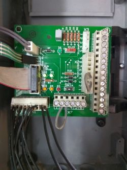
The attached photo shows the PCB "Manoeuvring card" of this system. At first glance, you can see that the X1 connector has fewer pins than, for example, the ECS940 version.

I'm trying to boot from disassembly, but there's a problem I can't seem to figure out. After turning on the power, the code E24 appears on the display, which according to found documents probably means: "(English) E24 Power failure. Normal error code after mains break or disengagement. Run the Door to fully open.”
When this code is displayed, the system only responds to the "open" button. This causes the motor to start in the opening direction, but it does not stop on its own. The only option to stop the engine is to press the Stop button.
Are any additional limit switches required for this controller?
Where can I connect the signal from the air strip sensor?
I am looking for an assembly manual/wiring diagram for the Crawford ECS950 + CDM9 gate controller.
On the forum I found documents regarding other versions of controllers (ECS930 / ECS940), although there are differences, e.g. in the connectors.
The attached photo shows the PCB "Manoeuvring card" of this system. At first glance, you can see that the X1 connector has fewer pins than, for example, the ECS940 version.

I'm trying to boot from disassembly, but there's a problem I can't seem to figure out. After turning on the power, the code E24 appears on the display, which according to found documents probably means: "(English) E24 Power failure. Normal error code after mains break or disengagement. Run the Door to fully open.”
When this code is displayed, the system only responds to the "open" button. This causes the motor to start in the opening direction, but it does not stop on its own. The only option to stop the engine is to press the Stop button.
Are any additional limit switches required for this controller?
Where can I connect the signal from the air strip sensor?


