logo elektroda
logo elektroda
X
logo elektroda

How to connect the photovoltaic installation to the switchgear in the building?

andrzejamp 18453 36
ADVERTISEMENT
Treść została przetłumaczona polish » english Zobacz oryginalną wersję tematu
  • #1 19306376
    andrzejamp
    Level 6  
    Hello, where should the phase wires from the inverter output be connected? Is it before the main switch in the switchgear or after the switch?
  • ADVERTISEMENT
  • #2 19306467
    retrofood
    VIP Meritorious for electroda.pl
    Behind the counter.
  • #3 19306489
    andrzejamp
    Level 6  
    The switchgear in the building is behind the meter. So each of the variants I asked about is behind the meter, both before and after the switch-disconnector. Does this mean full freedom just behind the counter?
  • #4 19306520
    retrofood
    VIP Meritorious for electroda.pl
    andrzejamp wrote:
    Does this mean full freedom just behind the counter?

    No, it doesn't. But if the security system of the installation itself and the layout of the PV installation are not known, what should I write to you? My crystal ball broke.
  • #5 19306588
    andrzejamp
    Level 6  
    What protections in the TNC-S installation in question should I provide: overvoltage, overcurrent, residual current?
    As for the AC output of the inverter, it has a standard arrangement of protective and protective devices at the output recommended by the manufacturer (Fronius). After these circuits we have a line with three phases, N and PE to be connected.
    How to connect the photovoltaic installation to the switchgear in the building?
  • #6 19306678
    Merio186
    Level 17  
    The RCD in the circuit with the inverter is not needed if you already want to give it according to the Fronius technical documentation. They give either 100mA or 300mA. You must check. Fronius still in DTR probably require proper grounding.
  • #7 19306706
    andrzejamp
    Level 6  
    And within the home switchboard itself, where should the phase wires from the photovoltaics be connected? Are there any established standards or guidelines for this?
  • ADVERTISEMENT
  • #8 19306852
    Merio186
    Level 17  
    andrzejamp wrote:
    And within the home switchboard itself, where should the phase wires from the photovoltaics be connected? Are there any established standards or guidelines for this?
    The inverter on the AC side is treated as a regular "permanently" connected device. It is no different from, for example, a boiler. According to the technical documentation, it can be additionally protected, e.g. by RCD. But on a 30mA RCD, it will trip it 90%. Surge arresters should be provided on the DC side. Switches, fuses depending on the design and requirements, conditions.

    Remember that if you run the installation yourself without authorization, you may have a problem with the acceptance of this installation by ZE and the fire brigade if it is required in your implementation.
  • #9 19306921
    andrzejamp
    Level 6  
    If the photovoltaic installation is treated as a permanent receiver, can it be connected behind the main switch, e.g. to a distribution block?
  • #10 19307029
    Anonymous
    Level 1  
  • #11 19307546
    Merio186
    Level 17  
    andrzejamp wrote:
    If the photovoltaic installation is treated as a permanent receiver, can it be connected behind the main switch, e.g. to a distribution block?
    Buddy, but you need to secure the line to the inverter somehow... you can't ignore it.
  • #12 19307560
    andrzejamp
    Level 6  
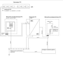
    In the diagram I attached above, the protections on the AC side of the inverter are marked. The switchgear in the building is connected to the GSU, GSU to the hoop iron, the PE conductor is earthed. There is a B+C arrester in the switchgear. What safeguards are still missing?
  • #13 19307597
    Anonymous
    Level 1  
  • ADVERTISEMENT
  • #14 19307642
    kkas12
    Level 43  
    andrzejamp wrote:
    In the diagram I attached above, the protections are marked.
    I'm sorry, but you're asking something that has already been answered.
    link
    In post 26 I wrote " The AC part may be located in the fuse board."
    The diagram to which I gave a link in the thread you mentioned and the one you posted have one common denominator.
    It is the fact that these PV installations have been somehow "glued" to the existing installations and fuse boards that protect them.
    Therefore, the AC part for the PV installation is outside the fuse board.

    You are going to use a new housing, put new cameras in it and make a new installation.
    So don't stick to these block diagrams, because in your case you don't have to mirror them exactly and you should successfully put the AC part where it belongs, ie in the new fuse board. You will install a 100mA RCD and a protection with a current adequate to what you mount on the roof.
    Then it will have arms and legs.
  • #15 19307709
    andrzejamp
    Level 6  
    I posted the diagram above for illustrative purposes because my colleagues asked about the protection on the AC side.
    Most diagrams are drawn like this.
    Which does not mean that the contents of the AC box will not be in the new switchgear.
  • #16 19307734
    kkas12
    Level 43  
    andrzejamp wrote:
    Which does not mean that the contents of the AC box will not be in the new switchgear.
    No, it doesn't, but it should be there! It should, because it's supposed to be a new table that is supposed to take into account the entire installation. So the PV part as well.

    And colleagues asked because you kind of forced these questions yourself by asking senselessly:
    andrzejamp wrote:
    Is it before the main switch in the switchgear or after the switch?

    andrzejamp wrote:
    ...can it be connected downstream of the main switch, e.g. to a distribution block?
  • #17 19307846
    andrzejamp
    Level 6  
    At the output of the AC box in the diagram I posted, there is a five-wire line that should be connected to the existing power line in the switchgear.
    (or it will already be in the switchgear in case of integration of the AC block with the switchgear).
    What is stupid in the question of where it is best to make this connection for individual phases and are there any rules that define it?
    In the discussion there were two answers that behind the meter and that PV installations should be treated like any fixed receiver.
  • #18 19307868
    kkas12
    Level 43  
    Buddy, you should put PV and RCD 100mA protection in the fuse board.
    Then you have both the meter and the main switch and you don't ask where to connect!
    And most importantly, you eliminate the section of the cable from which you cannot remove the voltage without turning off the power with the main switch.
    So it is and in God's way and as it should be.
  • #19 19307921
    andrzejamp
    Level 6  
    Thank you for all the information.
  • #20 19308358
    CYRUS2
    Level 43  
    andrzejamp wrote:
    In the discussion there were two answers that behind the meter and that PV installations should be treated like any fixed receiver.
    One false - nonsensical.
    The PV inverter should be treated as an additional power supply - not a load.
    The PV inverter works with the grid in a similar way as the generator.
  • #21 19308417
    andrzejamp
    Level 6  
    But I don't think calling the inverter a receiver or a source or both at the same time does not change the connection method in this case?
  • #22 19308457
    CYRUS2
    Level 43  
    andrzejamp wrote:
    But I don't think calling the inverter a receiver or a source or both at the same time does not change the connection method in this case?

    What does your friend think of the name? (all the same soup.......)

    The receiver, the source changes a lot.
    This has certain consequences in operation = in connection.

    With this attitude, a colleague should not deal with electricity.
    Because my friend is unable to understand the content of the texts and regulations.
  • ADVERTISEMENT
  • #23 19308512
    andrzejamp
    Level 6  
    If the opinions among professionals are divided, what should a person who is not associated with the industry on a daily basis think about it?
    If the inverter and gives and draws energy from the power line then what is it.
    Let a colleague enter into a polemic with other professionals speaking to me on this issue or write how he connects the inverter to the power line treating it as a generator.
  • #24 19308657
    CYRUS2
    Level 43  
    andrzejamp wrote:
    If the inverter and gives and draws energy from the power line then what is it.
    First of all, it's an inverter - not an inverter.
    The inverter does not draw power from the power line.
    The inverter only feeds the energy into the electricity grid or into the installation.
    Know what is it?
    andrzejamp wrote:
    or he will write how he connects the inverter to the power line treating it as a generator.
    There is no way to write how to connect.
    An installation project should be made after a site visit at the recipient's.
  • #25 19308670
    andrzejamp
    Level 6  
    And what is all the electronics in the inverter powered from?
  • #26 19308798
    retrofood
    VIP Meritorious for electroda.pl
    andrzejamp wrote:
    And what is all the electronics in the inverter powered from?

    It doesn't matter much. Note that modern electronics are more and more often supplied with a voltage in the range of 100 - 240 V. Switching power supplies, matched with the power parameter to the expectations of the powered device, can cope perfectly with voltage drops and distortions, without a negative impact on the operation of the powered equipment. Whether it's a TV or a converter.

    P.S. The inverters also work in the off-grid system, so without access to the grid.
  • #27 19309186
    andrzejamp
    Level 6  
    Each electronics consumes energy and the inverter also needs it when it does not produce it itself, e.g. at night.
    Just because she needs little doesn't mean she doesn't need it at all.
    Of course, we are talking about on-grid systems.
  • #28 21403329
    mm00007
    Level 3  
    I do not know whether the colleague who started the thread found out what he was asking or not.

    I will ask you.
    Where do I plug in the cable coming from the inverter? (Before or after the main switch; by main switch I mean the one in the house distribution, not the one at the meter).

    It seems to be before the circuit breaker so that I can be sure that when I turn it off, there is no power (even from the pv) in the house.
  • #29 21403345
    marcinradom
    Level 13  
    >>21403329 I have the wire from the inverter plugged into the installation behind the main switch. However, I can disconnect the PV from the rest of the installation with an isolation disconnect....
  • #30 21403362
    mm00007
    Level 3  
    So if something happens and you need to switch off the power in the chupa, you run to the switchboard and switch off the main switch and still have power from the inverter?

Topic summary

The discussion revolves around the proper connection of photovoltaic (PV) installations to building switchgear. Key points include the placement of phase wires from the inverter output, with suggestions to connect them behind the main switch or to a distribution block. The importance of protective devices such as RCDs (Residual Current Devices) and surge arresters is emphasized, particularly for the AC and DC sides of the inverter. The inverter is treated as a permanent power supply rather than a load, and adherence to standards like EN 60439-1 is recommended. The conversation also highlights the need for proper grounding and the potential implications of unauthorized installations on acceptance by utility companies.
Summary generated by the language model.
ADVERTISEMENT