logo elektroda
logo elektroda
X
logo elektroda

Induction loop, AC, DC protection and other questions related to PV installation

Spajder_PL 35163 42
ADVERTISEMENT
Treść została przetłumaczona polish » english Zobacz oryginalną wersję tematu
  • #1 18356639
    Spajder_PL
    Level 11  
    Recently, when looking for answers about induction loops, I came across the following article:
    Real and significant mistakes made when making photovoltaic installations Link

    which raised a few more questions for me, but in order:

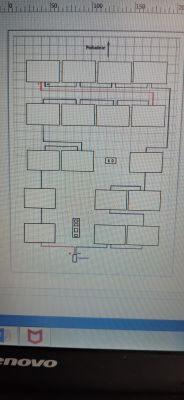
    1. Induction loop. Does it really matter and shouldn't be. My doubts were caused by this entry Link in which Longi Solar recommends connecting modules in a way that creates an induction loop. Unfortunately, in my case, the induction loops have also been created and I am thinking of submitting a complaint to the installation contractor

    2. Point 3 of the article: "Failure to make protective equipotential bonding" - do you have such connections made (unfortunately I do not have it, the structure is grounded, but not individual panels as in the article)

    3. Not installing an additional surge arrester when the distance between the panels and the inverter exceeds 10m. If the distance from the PV generator to the inverter exceeds 10m, an additional surge arrester should be installed at the panels. The limiter at the inverter remains unchanged - the distance for me is about 12-15 meters (to the first panel to the inverter - plus about 15 meters in the string) or should I have additional protection?

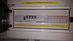
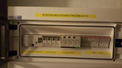
    4. Are the AC / DC protections correct? Induction loop, AC, DC protection and other questions related to PV installation
  • ADVERTISEMENT
  • #2 18356859
    theo33
    Level 27  
    This pic is illegible, but I don't see overvoltage protection on the DC side here
  • #3 18356878
    Spajder_PL
    Level 11  
    I put in a clearer picture Induction loop, AC, DC protection and other questions related to PV installation

    (I see, it came out not entirely clear either, I'll try to insert better tomorrow)
  • #4 18356908
    theo33
    Level 27  
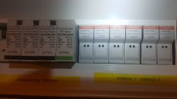
    read it on the right with red overprint, probably disconnectors
  • #5 18356917
    Spajder_PL
    Level 11  
    Mersen CUS101HEL 1000VDC 32A 10x38
    Induction loop, AC, DC protection and other questions related to PV installation
  • Helpful post
    #6 18356954
    theo33
    Level 27  
    These are disconnectors, it comes out that there are three strings, what inverter? could DC overvoltage protectors be built in because there is no such board in this table.

    After AC, the type 1 and 2 arrester is OK. C20A protection, but why C and why four-pole and this off. differential-current 100mA what it would serve and DC / AC circuits should be separated by some marked partition
  • ADVERTISEMENT
  • #7 18356992
    Spajder_PL
    Level 11  
    3 strings, Fronius Symo 12.5 inverter
  • Helpful post
    #8 18357126
    MichałS
    Level 35  
    As for the loop, it should be avoided not only in PV. What is a dipole? A loop tuned by its length to certain frequencies.
  • #10 18362654
    Spajder_PL
    Level 11  
    Thank you for your help so far.
    Installation done two weeks ago. I want to ask a contractor to correct the installation. I do not know how to motivate my request, I will try to refer to some regulations - on various pages I found references to standards (but I did not find individual standards - they are paid, and probably would not tell me much if I even read them).

    I am asking the experts of the subject for an opinion on what arguments to use so that the installation contractor would like to improve the work performed:

    1.addition of surge arresters on the DC side (PN-EN 61173: 2002, PN-EN 50539-11 standards)
    2.separate switchgear for AC and DC (I saw information on some website that the standard requires it, but I cannot find it now)
    3.removal of induction loops (In accordance with PN-EN 62305, the requirement is the elimination of induction loops in all installations outside and inside the building)
    4.adding the grounding of the panels (instructions for the panels)
  • #11 18363106
    MichałS
    Level 35  
    The question is whether the installation was created as part of a municipal program?
  • #12 18363186
    Spajder_PL
    Level 11  
    It was not a communal program, nor any other. Order without subsidy (Except "My current", documents not yet submitted).
  • ADVERTISEMENT
  • #13 18364317
    theo33
    Level 27  
    Spajder_PL wrote:
    Thank you for your help so far.
    Installation done two weeks ago. I want to ask a contractor to correct the installation. I do not know how to motivate my request, I will try to refer to some regulations - on various pages I found references to standards (but I did not find individual standards - they are paid, and probably would not tell me much if I even read them).

    I am asking the experts of the subject for an opinion on what arguments to use so that the installation contractor would like to improve the work performed:

    1.addition of surge arresters on the DC side (PN-EN 61173: 2002, PN-EN 50539-11 standards)
    2.separate switchgear for AC and DC (I saw information on some website that the standard requires it, but I cannot find it now)
    3.removal of induction loops (In accordance with PN-EN 62305, the requirement is the elimination of induction loops in all installations outside and inside the building)
    4.adding the grounding of the panels (instructions for the panels)


    first of all, it is trying to enforce such technical arrangements or provisions that were given in the offer, if there were no technical arrangements, ask the contractor for explanations and arguments why it is not the way you see it
  • #14 18371751
    Spajder_PL
    Level 11  
    At the beginning of January, I have an appointment with the PV installation contractor.
    One more question bothers me. What does it mean that:

    "The cables used in the process of connecting the surge arresters should be relatively short. The length of the cables connecting the surge arrester with the power cable and the potential equalization bus should not be longer than 0.5 m" -

    At the moment, a 5-wire cable goes from the switchgear with AC surge arresters (photo a few messages back), which is connected to the existing installation and to the so-called "coopers". The length of this cable is approximately 10 meters .
    Does that mean it is badly done?
    Would it be correct if the switchgear was placed in the place where it is connected to the existing installation (right next to the hoop iron) or if there was a separate earthing wire from the hoop to the already made switchgear?
    Sorry for a stupid question, but I don't know anything about it and I don't quite understand what it means: "Cable length connecting the limiter with the power cord and the potential equalization rail "
  • ADVERTISEMENT
  • #16 18371926
    Spajder_PL
    Level 11  
    Thank you for the link, I have read this article before (read it again) and yet one thing is still unclear to me:

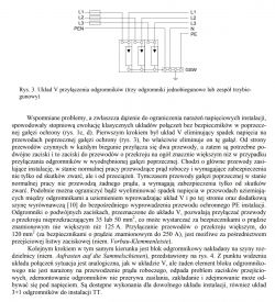
    "And again, in order for the device to fulfill its role, it is necessary to consider not only the location of the arrester in the wiring diagram, but also the method of its mounting and connection in the facility, including installation details: sufficient cross-section of the wires, the shortest possible length of the conductors of the transverse protection branch, in principle not exceeding 0.5 m on each side , avoiding loops and sharp bends. "

    The length of 0.5 meters is still coming back - in this article it is called "the length of the wires of the transverse protection branch".
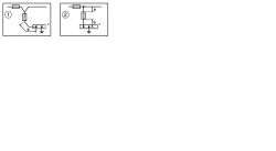
    What is the transverse branch of protection? Is this the line segment marked with the letter a in the figure below?
    Induction loop, AC, DC protection and other questions related to PV installation
  • #17 18372514
    BikeBarian
    Level 24  
    Link

    Page 5,6,7 and especially 7 and this is:

    Induction loop, AC, DC protection and other questions related to PV installation

    If you connect in a V system, you eliminate this branch of protection. You need a good-class limiter, such as in my promoted topic (not necessarily so expensive, but for probably PLN 700 you will find something from Dehn with double clamps)
    Link

    It would also be good, as in this picture, to connect the "ground" part in the V system, but it is not always possible because not everyone has a GSW / GSU near the switchgear, not to mention the PV switchgear which is often and densely located in a completely different room.
  • #18 19007233
    aadler57
    Level 6  
    Hello, I would like to connect to the topic I have a photovoltaic installation or there is an induction loop in this diagram, if so, how to solve it Induction loop, AC, DC protection and other questions related to PV installation
  • #19 19007328
    wello
    Level 20  
    A beautiful loop, it's nice. In this case, simply run the wire (whether + or -) along the other wire. It'll take a while, but at least there won't be a loop.
  • #20 19007353
    aadler57
    Level 6  
    So I thought I will have to talk to the contractor thanks for the answer.

    Added after 10 [minutes]:

    well, I have a request and if you could mark me where this loop is because I don't get it, thanks
  • #21 19007385
    retrofood
    VIP Meritorious for electroda.pl
    aadler57 wrote:

    well, I have a request and if you could mark me where this loop is because I don't get it, thanks

    Do you know what a loop is? This is the usual meaning of the word. Illustratively, you won't stick your head into a rope to hang yourself, you have to make a loop of it.
    Now take a look at your drawing. Is it possible to put the head in there? Da! And you'll have a cord around your neck.
    Just hang yourself.
  • #23 19007473
    retrofood
    VIP Meritorious for electroda.pl
    aadler57 wrote:
    Now I understand

    Well, the point is that "if someone puts this head in there", this closed loop should not be there. That this circle would not close. Why is it so important? Well, try to read such a study, maybe something will be explained.
    The effects of lightning discharges
    I especially recommend the fragment "Effects of the magnetic field"
  • #24 19007523
    aadler57
    Level 6  
    Thank you for your answer
  • #25 19325550
    kddktech
    Level 2  
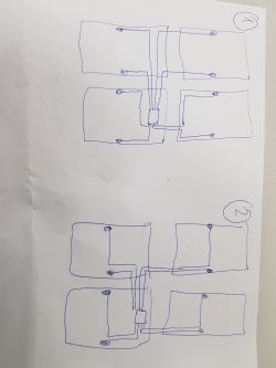
    Gentlemen, what about induction look like with microinverters? Are both ways good or is case 1 creating a loop with each panel? Induction loop, AC, DC protection and other questions related to PV installation
  • #27 19325845
    kddktech
    Level 2  
    Thanks for the hint.
    Well, only in the case of No. 2 you have to extend one wire on each panel and then there are more MC4 connections. I don't know what's better?
  • #28 19326528
    BikeBarian
    Level 24  
    kddktech wrote:
    Thanks for the hint.
    Well, only in the case of No. 2 you have to extend one wire on each panel and then there are more MC4 connections. I don't know what's better?


    If you have to add MC4 connectors, solution no. 1 will be better. These loops are relatively small and there are several loops of them instead of one big one. And in most cases, PV fires are caused by faulty connections of connectors or their poor quality.
  • #29 19361112
    maniek763
    Level 11  
    wello wrote:
    A beautiful loop, it's nice. In this case, simply run the wire (whether + or -) along the other wire. It'll take a while, but at least there won't be a loop.


    I see that your colleague you wrote that he has a loop, and what if his drawing shows three planes of the roof separated from each other. The manufacturer Znshine shows the connection instructions and the perfect connection is shown and with a higher risk but not forbidden, the distance of the wires is about 3m I guess.
  • #30 19364270
    maniek_ole
    Level 9  
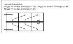
    Hello, I am setting up 9.9 kWp PV installations. 22 Longi 450W modules. 1 table 4 rows horizontally. There will be 6 modules in two rows, and two more rows of 5 modules. These are large panels as the dimension is 2094x1038 and they have 1.4m long wires.
    My question is how best to connect in order not to avoid induction loop?
    In the assembly manual, the manufacturer presents the connection diagram as shown in the picture.

    Induction loop, AC, DC protection and other questions related to PV installation

    Will it be the correct connection ??

Topic summary

The discussion revolves around concerns related to photovoltaic (PV) installations, specifically focusing on induction loops, protective equipotential bonding, and surge protection. The main inquiry addresses the significance of induction loops in PV systems, referencing a recommendation from Longi Solar that inadvertently creates such loops. Participants discuss the necessity of protective bonding, the installation of surge arresters when the distance between panels and inverters exceeds 10 meters, and the implications of not adhering to standards like PN-EN 61173:2002 and PN-EN 50539-11. Various responses highlight the importance of avoiding induction loops, the correct placement of surge protectors, and the need for proper grounding of panels. The conversation also touches on the technical aspects of wiring and the potential risks associated with improper installations.
Summary generated by the language model.
ADVERTISEMENT