The electronic components market provides designers with many models of resistors, characterized by an extremely wide range of values, as well as other intrinsic characteristics. Reliable measurement of the resistive value of a component is fairly simple for values between 2 Ω and 2 MΩ. For values lower than 2 Ω, measurement issues can be found, as this low value is also affected by the presence of the test leads of the measuring instrument, and in addition, an average tester is limited to measuring the most common resistances. We will now explain how to measure, with sufficient accuracy, very low-value resistances without buying expensive equipment.
The simplest solution: buy a milliohm meter
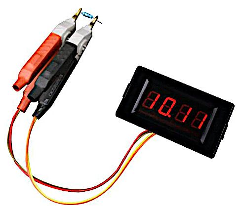
Electronics is mathematics, and here, too, Ohm’s Law lends us a big hand. A simple method is to use an ohm meter dedicated to this functionality (see Figure 1), which can be purchased on the internet at an extremely low price. To use such devices, it is sufficient to connect the element to be measured (a low-value resistor or even a piece of conductive metal) to read immediately on the display the resistive value of the component, expressed in milliohms.

Figure 1: A milliohm meter can be purchased on the internet at an extremely low price.
Ohm’s Law helps us again
To measure the ohmic value of a resistor with a low ohmic value (less than 2 Ω), it is possible to perform the operation using another resistor of known value, which is much higher than the unknown resistor (say about 1,000×). The essential condition is to know the exact value of the known resistor, but this observation is quite trivial, as its value falls within the measurable range, and with any tester, one can easily trace the measurement. The following practical example will help clarify the concept better.
A practical example
For the execution of various measurement tasks, obtain the following materials:
• A mid-range tester
• A 100-Ω resistor of at least 5 or 10 W
• A stabilized power supply of any value, excluding any kinds of batteries
• The unknown resistor to be measured, with a very low value
• A calculator (optional)
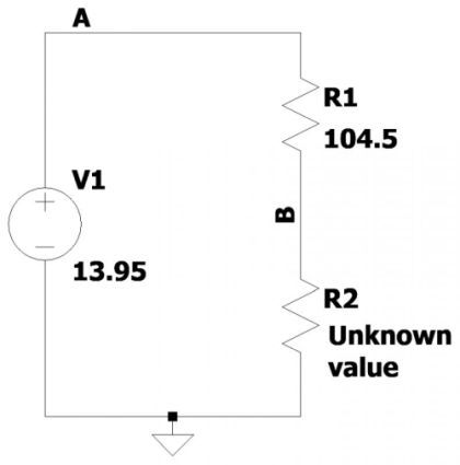
The first step is to measure, with the highest possible accuracy, the resistor of known value. Its nominal resistance is 100 Ω (as specified in the list above), but actually, its value may be slightly different due to component tolerances. A resistor of 100 Ω with a tolerance of 1% should be chosen, if possible. In any case, with the tester, it is necessary to measure such a resistor. Assume that the measurement returns the value of 104.5 Ω. Now, it is necessary to make the connection in Figure 2. This is a simple series connection between the power supply, resistor R1 (with a value of 104.5 Ω) and resistor R2 (with an unknown value).

Figure 2: The wiring diagram to be made
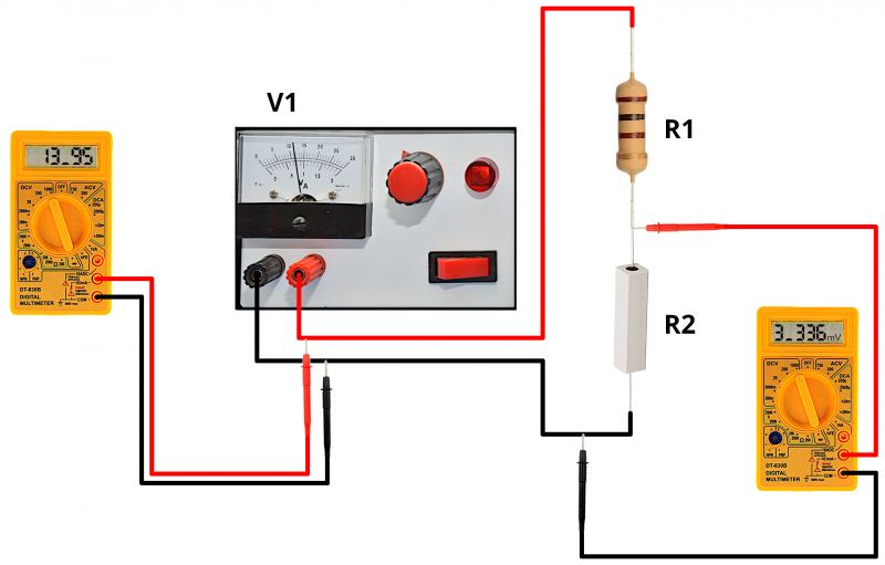
Follow the wiring diagram shown in Figure 3 to get a good understanding of the connections and measurements to be made. Turn on the power supply and measure with the tester the voltage at its ends. This is basically the voltage present between Point A of the circuit and ground (GND). Suppose the nameplate data shows a voltage of 13.8 V but the actual measurement with the tester returns a value of 13.95 V.
Then measure, again with the tester, the voltage present between Point B of the circuit and ground (GND). In the example, the tester returns a measurement of 3.336 mV, equivalent to 0.003336 V, which, in practice, is also the voltage present at the ends of resistor R2:
V(B) = V(R2) = 0.003336 V
At this point, it is possible to know the voltage present at the ends of resistor R1, as we have the voltage at Node A and the voltage at Node B. It is calculated simply by calculating the difference between these two voltages:
V(R1) = V(A) – V(B) = 13.95 V – 0.003336 V = 13.946664 V
We now know the voltage across resistor R1 and its ohmic value, so it is possible to calculate the electric current flowing across it, using Ohm’s Law. Note that the current flowing on resistor R1 is the same as the current flowing on resistor R2. Carry out the following division:
I(R1) = V(R1) / R(R1) = 13.946664 V / 104.5 Ω = 0.13346 A
As mentioned before, the current flowing on resistor R1 is the same as the current flowing on resistor R2, so:
I(R1) = I(R2) = 0.13346 A
Finally, we are able to calculate the ohmic value of the unknown resistor, once again using Ohm’s Law. The data we need are the voltage across resistor R2 and the current flowing through it:
R(R2) = V(R2) / I(R2) = 0.003336 / 0.13346 = 0.024996 Ω
The unknown resistor, although not specified above, has a nominal value of 0.025 Ω.
Conclusion
This method for measuring low-ohmic–value resistors is very powerful and based on the fact that it is much easier to measure a 100-Ω resistor with great accuracy using a simple and inexpensive tester. Such a 100-Ω resistor is used as a tool for calculating the current flowing through the circuit and must dissipate a great deal of power, so it is recommended to use one of at least 5 or 10 W.
Below, we summarize the steps to be taken:
• Accurately measure the value of the known resistor of 100 Ω, for which the tester returns a value of 104.5 Ω.
• Make the connection diagram, which involves wiring the components in series.
• With the components connected, the voltage of the 13.8-V power supply should be measured. In this case, the measurement with the tester returned the voltage of 13.95 V.
• Measure with the tester the voltage between Point B of the circuit and ground (GND): The device returned the value of 0.003336 V.
• Calculate the voltage across resistor R1: 13.95 V – 0.003336 V = 13.946664 V.
• Calculate the current flowing through R1: 13.946664 V / 104.5 Ω = 0.13346 A.
• The currents on R1 and R2 are equal: I(R1) = I(R2) = 0.13346 A.
• Calculate the value of the unknown resistor: R(R2) = V(R2) / I(R2) = 0.003336 / 0.13346 = 0.024996 Ω.
With this method, unknown resistors with low ohmic value will have no more secrets for you.
The simplest solution: buy a milliohm meter
Electronics is mathematics, and here, too, Ohm’s Law lends us a big hand. A simple method is to use an ohm meter dedicated to this functionality (see Figure 1), which can be purchased on the internet at an extremely low price. To use such devices, it is sufficient to connect the element to be measured (a low-value resistor or even a piece of conductive metal) to read immediately on the display the resistive value of the component, expressed in milliohms.

Figure 1: A milliohm meter can be purchased on the internet at an extremely low price.
Ohm’s Law helps us again
To measure the ohmic value of a resistor with a low ohmic value (less than 2 Ω), it is possible to perform the operation using another resistor of known value, which is much higher than the unknown resistor (say about 1,000×). The essential condition is to know the exact value of the known resistor, but this observation is quite trivial, as its value falls within the measurable range, and with any tester, one can easily trace the measurement. The following practical example will help clarify the concept better.
A practical example
For the execution of various measurement tasks, obtain the following materials:
• A mid-range tester
• A 100-Ω resistor of at least 5 or 10 W
• A stabilized power supply of any value, excluding any kinds of batteries
• The unknown resistor to be measured, with a very low value
• A calculator (optional)
The first step is to measure, with the highest possible accuracy, the resistor of known value. Its nominal resistance is 100 Ω (as specified in the list above), but actually, its value may be slightly different due to component tolerances. A resistor of 100 Ω with a tolerance of 1% should be chosen, if possible. In any case, with the tester, it is necessary to measure such a resistor. Assume that the measurement returns the value of 104.5 Ω. Now, it is necessary to make the connection in Figure 2. This is a simple series connection between the power supply, resistor R1 (with a value of 104.5 Ω) and resistor R2 (with an unknown value).

Figure 2: The wiring diagram to be made
Follow the wiring diagram shown in Figure 3 to get a good understanding of the connections and measurements to be made. Turn on the power supply and measure with the tester the voltage at its ends. This is basically the voltage present between Point A of the circuit and ground (GND). Suppose the nameplate data shows a voltage of 13.8 V but the actual measurement with the tester returns a value of 13.95 V.
Then measure, again with the tester, the voltage present between Point B of the circuit and ground (GND). In the example, the tester returns a measurement of 3.336 mV, equivalent to 0.003336 V, which, in practice, is also the voltage present at the ends of resistor R2:
V(B) = V(R2) = 0.003336 V
At this point, it is possible to know the voltage present at the ends of resistor R1, as we have the voltage at Node A and the voltage at Node B. It is calculated simply by calculating the difference between these two voltages:
V(R1) = V(A) – V(B) = 13.95 V – 0.003336 V = 13.946664 V
We now know the voltage across resistor R1 and its ohmic value, so it is possible to calculate the electric current flowing across it, using Ohm’s Law. Note that the current flowing on resistor R1 is the same as the current flowing on resistor R2. Carry out the following division:
I(R1) = V(R1) / R(R1) = 13.946664 V / 104.5 Ω = 0.13346 A
As mentioned before, the current flowing on resistor R1 is the same as the current flowing on resistor R2, so:
I(R1) = I(R2) = 0.13346 A
Finally, we are able to calculate the ohmic value of the unknown resistor, once again using Ohm’s Law. The data we need are the voltage across resistor R2 and the current flowing through it:
R(R2) = V(R2) / I(R2) = 0.003336 / 0.13346 = 0.024996 Ω
The unknown resistor, although not specified above, has a nominal value of 0.025 Ω.
Conclusion
This method for measuring low-ohmic–value resistors is very powerful and based on the fact that it is much easier to measure a 100-Ω resistor with great accuracy using a simple and inexpensive tester. Such a 100-Ω resistor is used as a tool for calculating the current flowing through the circuit and must dissipate a great deal of power, so it is recommended to use one of at least 5 or 10 W.
Below, we summarize the steps to be taken:
• Accurately measure the value of the known resistor of 100 Ω, for which the tester returns a value of 104.5 Ω.
• Make the connection diagram, which involves wiring the components in series.
• With the components connected, the voltage of the 13.8-V power supply should be measured. In this case, the measurement with the tester returned the voltage of 13.95 V.
• Measure with the tester the voltage between Point B of the circuit and ground (GND): The device returned the value of 0.003336 V.
• Calculate the voltage across resistor R1: 13.95 V – 0.003336 V = 13.946664 V.
• Calculate the current flowing through R1: 13.946664 V / 104.5 Ω = 0.13346 A.
• The currents on R1 and R2 are equal: I(R1) = I(R2) = 0.13346 A.
• Calculate the value of the unknown resistor: R(R2) = V(R2) / I(R2) = 0.003336 / 0.13346 = 0.024996 Ω.
With this method, unknown resistors with low ohmic value will have no more secrets for you.


