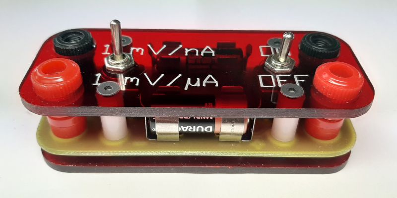
I came across a project once David Jones uCurrent .
All in all, it is a very simple system. Voltage is deposited on the measuring resistor, which is then amplified x100 and fed to the output.
Unfortunately, the item is not cheap, about 70 EUR excluding shipping costs.

I decided to make my version, slimmer, cheaper, but with similar (or even better in some respects) parameters.
What did I not like about the original?
- Power. One CR2032 battery and artificial zero. The circuit is complicated (like one opamp, but always), and the power supply of the output amplifier is only +/- 1.5 V.
- The use of two expensive and hard to reach opamps in the amplifier. The cascade circuit improves the frequency response a little compared to one amplifier with higher gain, but is megahertz important, for example, when measuring the current consumed by the circuit in the sleep state?
Changes made by me:
- Two ranges instead of three. Each multimeter measures the milliamps, and for the oscilloscope you can use a resistor in series.
- Easily available operational amplifier - you can buy it at TME.
- Power supply from two 12 V batteries. This gives an output voltage range from 0 to 10,000 mV, so in the nA range I can measure currents from 0 to 10 uA, and in the uV range up to 10 mA. This is 10 times more than the original.
- Place for a diode protecting the amplifier input. Just in case.
- I also resigned from the battery voltage monitoring system.
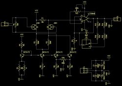
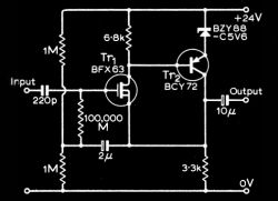
Thus, the layout was created as in the diagram. Simple, not to say primitive.
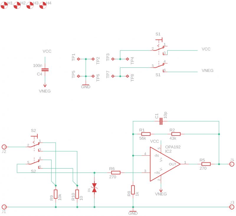
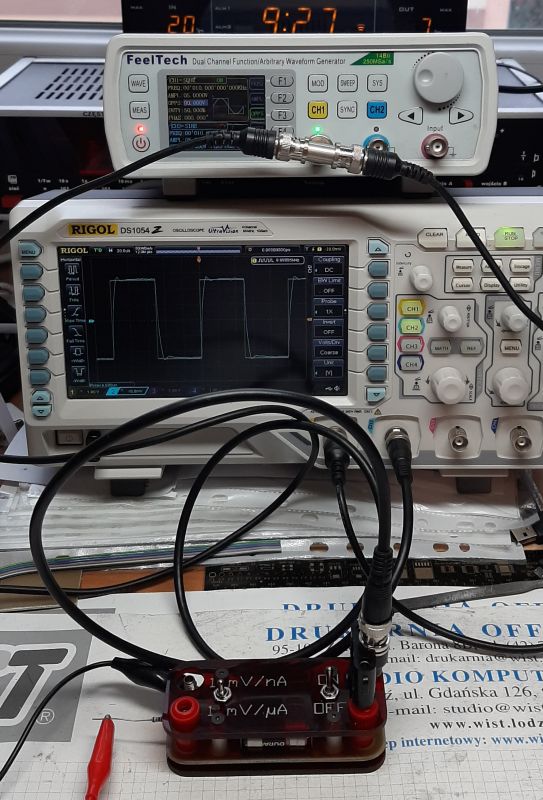
The value of the capacitor C1 has been transferred from the original schematic - if necessary, I will try to improve the compensation using a generator and an oscilloscope.
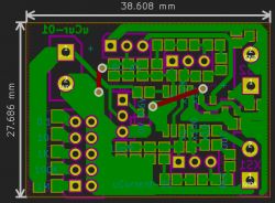
A tile pattern was created behind the diagram. As the scheme is simple, the board came out in one layer without any problems, without combining with bridges etc. Easy to make at home.
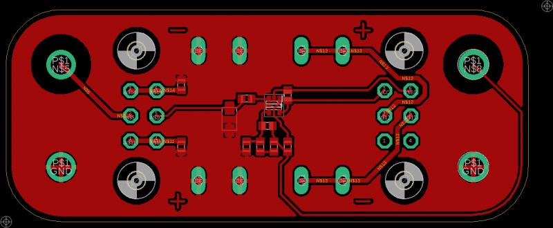
And then the layout itself.
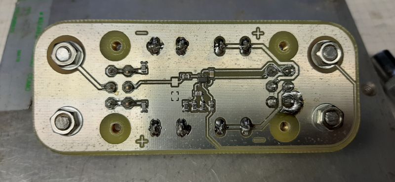
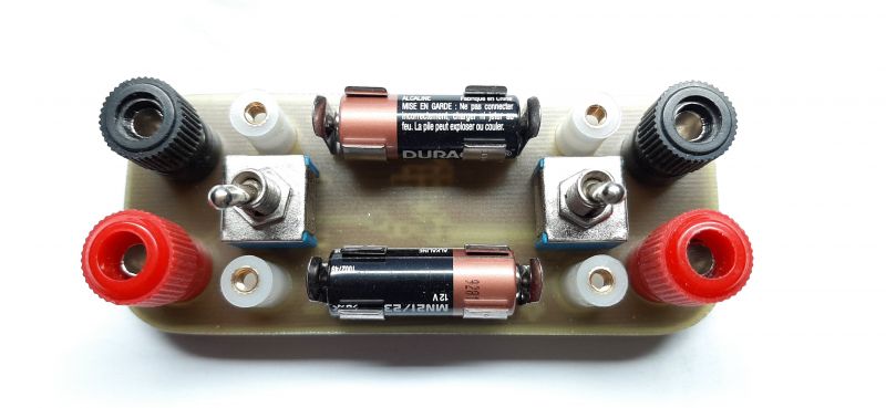
0.1% resistors
Time for measurements:
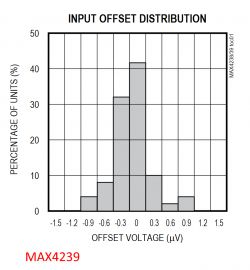
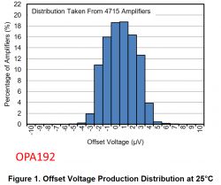
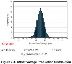
The offset voltage is less than 1 mV. With the input shorted, the output voltage fluctuates in the range of 0.3 to 0.8 mV.
The accuracy of indications is surprisingly high, better than 0.5%. But I assume it will be safe to assume 1%. Calculated using the technical method, because I have nothing to calibrate this device with. Yet the meters I use to measure voltage and resistance have their limitations.
The voltage source was a 3V battery, a current limiting resistor in series and my adapter. The voltage is measured at the ends of this series circuit, and its total resistance, including the leads, is measured with a multimeter.
For the uA range:
At the entrance = 3.1630 V, R = 99 890 ?
And the theory. = 31.6 uA
And d. = 31.8 uA
error = 0.42%
For the nA range:
At the entrance = 2.9434 V, R = 5134000 ?
And the theory. = 573.3 nA
And d. = 574.4 nA
error = 0.19%
Enough for me.
Cool? Ranking DIY


