logo elektroda
logo elektroda
X
logo elektroda

Grundig 40 VLE 5730 BN Power Board ZUV 194R-06 Schematic Needed

draganp 498 9
ADVERTISEMENT
  • #1 21355341
    draganp
    Level 3  
    Mark: Grundig
    Model: 40 VLE 5730 BN

    Hello, I'm looking for a schematic of the power board ZUV 194R-06. It is from the Grundig VLE 5730 LED TV.

    Thanks
  • ADVERTISEMENT
  • #2 21355835
    Lolo81700
    Level 12  
    Hello my dear.
    What is the problem with the power board?
  • ADVERTISEMENT
  • #4 21356559
    draganp
    Level 3  
    Lolo81700 wrote:
    Hello my dear.
    What is the problem with the power board?


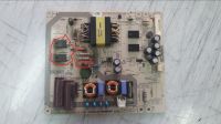
    Hello, the fuse was blown. Both MOSFETs were shorted, fusible resistor blown too, capacitor (101K 1KV) damaged. Replaced all and now the board is not shorted. Fuse is OK, but there is no 5V standby voltage.
    Marked parts that I've replaced.

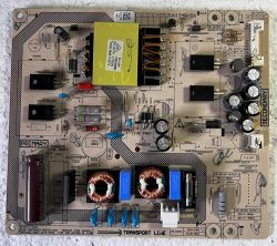
    If you have any idea please let me know. I can post better photos of both sides..maybe it would be helpful....
  • ADVERTISEMENT
  • #5 21356637
    Lolo81700
    Level 12  
    What is the chassis model? See on the label
  • ADVERTISEMENT
  • #6 21356696
    draganp
    Level 3  
    >>21356637
    I am not with TV now, but as I remember the chassis is GM.
  • #7 21356762
    lisek
    Service technician RTV
    Quote:
    but there is no 5V standby
    .
    What IC (TNY>>>) is used or solution with transistor ?
  • #8 21358798
    draganp
    Level 3  
    I have only a basic knowledge about electronics and hope this attached photo with marked parts is helpful.
    If you have an idea what I need to test/replace please let me know.
  • #9 21359205
    lisek
    Service technician RTV
    Quote:
    no 5V standby / no 5V stby
    .
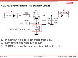
    On pcb PSU not 5V stby , only +12V and GND and EN (enable)

    Grundig 40 VLE 5730 BN Power Board ZUV 194R-06 Schematic Needed

    Maybe you have such a solution stby +5V
    - it's from a different power supply model
    5V StandBy Circuit diagram on 17IPS71 board
  • #10 21360483
    draganp
    Level 3  
    There is no DC voltage on the secondary side. I wrote that there is no standby voltage because standby voltage, I think, should be there as soon as there is AC voltage 230v present.

Topic summary

The discussion revolves around a request for a schematic of the power board ZUV 194R-06 from the Grundig 40 VLE 5730 BN LED TV. The user reports that after replacing several damaged components, including MOSFETs, a fusible resistor, and a capacitor, the board is no longer shorted, but there is no 5V standby voltage present. Other participants inquire about the chassis model and suggest checking specific integrated circuits (ICs) and voltages on the power supply unit (PSU). The user confirms that there is no DC voltage on the secondary side and emphasizes the expectation of standby voltage when AC power is applied.
Summary generated by the language model.
ADVERTISEMENT