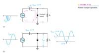
I am currently studying how Diode Clampers works. (Sorry for the newbie question.)
Regarding the picture on the attachments. On the result waveform after applying clampling / shifting techniques, I am wondering where did the -0.7 V on the graph came from?
On the negative alternation, the Vp(out) is equal to 0 V as no current flows through the load resistor.On the positive alternation, the Vp(out) is equal to 2 Vp(in) - 0.7 from KVL (Vp(in) + Vp(in) - 0.7 - Vp(out) = 0)The Vp(in) - 0.7 on the graph shows the new / considered / assumed origin to show that the waveform did not change shape but only shifted upwards. But I have no Idea why the -0.7 V is labeled there? Wherein on the negative alternation, there was no 0.7 V to get but only the 0 V from the load resistor, hence why the negative part shifted there..
Again, sorry for the newbie question but I would appreciate any help. Thank you in advance.


