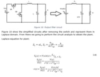
I'm final year student currently designing a buck converter with an analogue controller (LM2743). What my supervisor told me is to used a PI controller using bode plot. My design spec: 1. Vin=12V 2. Vout=5V 3. Pout=10Watt 4. Fsw=100KHZ From there I obtained my inductor (48.6uH), output capacitor (15uF) an load resistor at (2.5ohm). From there my transfer function is:
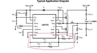
From there I'm quite stuck on how to do it. Where I know the T.F for PI controller is Gc(s)=Kp+(ki/s). After that, lets say I've managed top design the PI controller. From datasheet LM2743, there are few components need to be connected to the main controller which is pin FB and EAO.
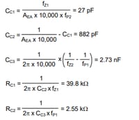
Its mentioned in the data sheet that the calculation can be made using the equation given but didn't tell on how to get the Fz1, Fz2, Fp1 and Fp2 where these value that can decide the components.


