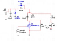
I am designing a buck converter to be used to power a load from a solar panel (100v OCV max). The load is 48v, 8A maximum. I have been trying to simulate this circuit to get an idea of the voltage and current ripple using NI MultiSim, but the transient analysis often fails or is total nonsense. I have found plenty of resources for calculating the values of my components, but often they are not for the low-side switching I am trying to do. I have the mosfet, schottky diodes, and inductor already, but I could get different ones if need be. I have selected the MIC5014 high/low side gate driver to be controlled by a 5v pwm signal. I am looking for design resources, as well as some direction on how I can determine if these parts will indeed work together. I would normally tinker with the parts, but I am afraid of damaging the load and/or myself with such high power. I also have little experience with generating high frequencies (I am using an arduino at the moment.) Any help is much appreciated!
Note: 12ohm load is shown, as well as a voltage sense circuit with a RC filter. I plan to be able to sense the voltage across the load this way in order to regulate it via a microcontroller.
Note: 12ohm load is shown, as well as a voltage sense circuit with a RC filter. I plan to be able to sense the voltage across the load this way in order to regulate it via a microcontroller.


