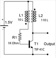
What load are you intending to drive with this circuit? What output voltage do you read with your voltmeter set to read AC voltage? Try swapping the voltmeter leads while reading DC: If the two readings are not negatives of each other, you know the waveform is confusing your voltmeter. The waveform on an oscilloscope should oscillate between 0V and about +(1.5V - 0.7V) *12 = +10V with respect to the transistor emitter. You could explore the output polarity by connecting a 10K ohm resistor in series with an LED, and trying connecting the resistor and LED both ways across the emitter and collector. In the polarity where the LED lights, you could add more series LEDs until they don't light, to get some idea of the peak voltage in the waveform.
I've seen this circuit (with both coil windings 20 turns) used to drive a white LED, cathode connected to transistor emitter and anode connected to transistor collector, where the oscillator serves as both a voltage booster and a current limiter.


