Elektroda.com
Elektroda.com
X

Set - DC / DC converter 9A XL4016 and panel meter DSN-VC288, assembly, test

TechEkspert 55776 163
This content has been translated flag-pl » flag-en View the original version here.
  • Set - DC / DC converter 9A XL4016 and panel meter DSN-VC288, assembly, test
    Soon in Elektroda.pl gadgets A kit will appear that allows you to build a simple regulated power supply with voltage and output current readout. Inverter module descriptions DC / DC buck 9A 300W 1.2V-35V and a panel current and voltage meter DSN-VC288 can be found at elektroda.pl. After completing the set with a direct current source (e.g. unnecessary laptop power supply, transformer with rectifier and capacitor), you will get a simple regulated power supply. For the convenience of adjustment, the assembly potentiometer can be replaced with a multiturn potentiometer equipped with a knob.

    The DC / DC converter, apart from voltage regulation (CV operation), also allows for current limit regulation or CC operation. The impulse converter is based on the XL4016 chip and enables voltage regulation in the range of 1.2V-35V, maximum output current 9A. Input voltage in the range of 8-40V. Details can be found in the description: https://www.elektroda.pl/rtvforum/topic3434421.html
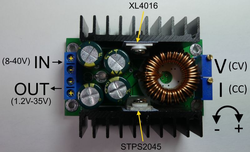
    Set - DC / DC converter 9A XL4016 and panel meter DSN-VC288, assembly, test

    The panel meter has a moderate accuracy of indications, we can try to improve it using mounting potentiometers placed on the module's board.
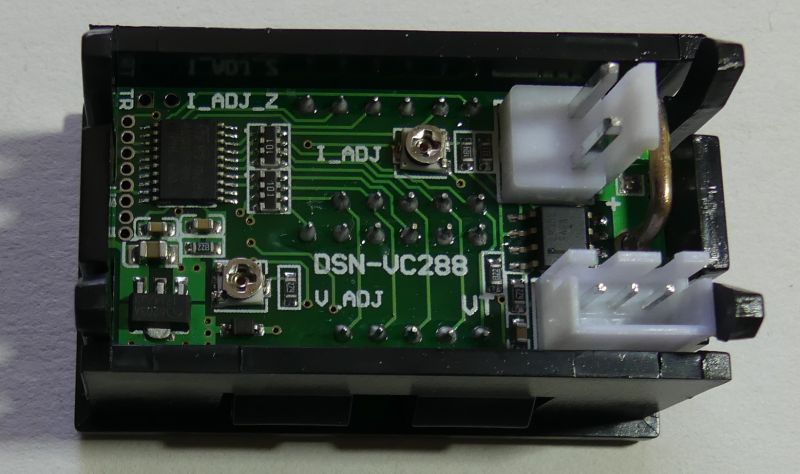
    Set - DC / DC converter 9A XL4016 and panel meter DSN-VC288, assembly, test

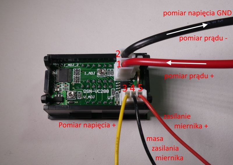
    The LED panel meter can be powered from a separate voltage source (or e.g. from an isolated AIMTEC DC / DC converter). Supply voltage is applied to wires 4 (GND) and 5 (+). When powered by 12V, the system consumes a current of about 20mA. Apply the voltage measured in relation to the wire 2 (GND) on the wire 3. Depending on the source, module suppliers provide the permissible supply voltage in the range of 4.5-24V. The system can be powered from the measured voltage or from the voltage at the converter input, then the wire 4 is left unconnected (the mass of the system is on the wire 2).
    Set - DC / DC converter 9A XL4016 and panel meter DSN-VC288, assembly, test

    It is important that the voltage supplying the meter does not exceed 24V (other sources indicate 28V or 30V). The converter can work with voltages as high as 35-40V. In such a situation, a stabilizer should be placed in the power supply circuit of the meter (wire 5), e.g. + 12V, the wire 4 is not connected.

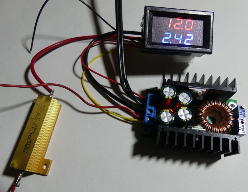
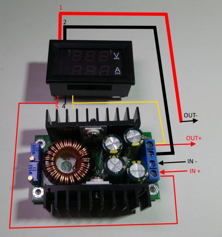
    The current is measured in the circuit of the measuring resistor on leads 1 and 2. Below is a diagram of the module connection (for supply voltages up to 24V) and a view of the practically connected modules. A 4.7om resistor simulating the receiver is connected to the output.
    Set - DC / DC converter 9A XL4016 and panel meter DSN-VC288, assembly, test Set - DC / DC converter 9A XL4016 and panel meter DSN-VC288, assembly, test

    It is worth paying attention to the set's output cable, which acts as the output GND. This is the red lead of 1 meter. Be careful not to confuse the polarity as the red wire is usually + power. A comprehensive description of the panel meter can be found here: https://www.elektroda.pl/rtvforum/topic3444499.html

    It is worth completing the whole with a housing and replacing both mounting potentiometers of the converter for voltage regulation and current limitation, with multi-turn potentiometers with knobs mounted on the front panel of the housing. It is worth to lead the output voltage to the terminals mounted in the housing. The source of voltage can be a traditional transformer, rectifier and a ripple smoothing capacitor, but you can also use a recycled switching power supply, e.g. from a laptop, printer, etc. The built power supply will have its limitations, but it can be useful in many workshops for "rough" measurements and powering less demanding circuits.

    Let me know what results can be obtained with the use of the presented set.

    Cool? Ranking DIY
    About Author
    TechEkspert
    Editor
    Offline 
    TechEkspert wrote 4622 posts with rating 3759, helped 12 times. Been with us since 2014 year.
  • #2
    Songo85
    Level 2  
    Some time ago I built a similar circuit to a rectifier (I had a rectifier that gave about 18-20V). It was ok for a quick recharge, but I couldn't leave it all unattended. After installing the converter and the meter, everything is great (the potentiometers were placed on the rectifier panel, which definitely makes the adjustment easier for me), but I have one question. What will happen when I connect the battery the other way round (without connecting the power supply, of course).
  • #3
    maciek_90
    Level 13  
    If you connect the outputs in reverse, they will probably blow out the capacitors on the inverter output first. Unfortunately, most of these cheap Chinese inverters do not have reverse connection protection.
  • #4
    mariomario
    Level 18  
    I have the same converter (powered by 2x12V power supplies connected in series, giving max. 24V and about 4A). I, in order to protect against reverse connection of batteries / accumulators to this inverter - I connected it at its output in parallel 3pcs SBL2040CT TO220 Schottky diodes from ATX power supplies (diodes connected, of course, in reverse), all placed on the heat sink. Such a simple protection will take over all the current when we connect the battery the other way round - but you have to be careful with the maximum current that they can "bear", for me 3 pcs should withstand theoretically (according to the specifications of these diodes) up to 120A current (3 SBL2040CT diodes, and in each housing of such SBL2040CT diodes there are - 2 pcs of schottky diodes, i.e. there are 6 pcs in total)
  • #5
    Songo85
    Level 2  
    In that case, would it be a good idea to add an ordinary rectifier diode in series and connect the voltage measurement after this diode. Let's say a diode at 10-20A. Are there perhaps better options for securing such a system?
    I also see a problem with the reverse polarity of the "measurement system" which, as I guess, will not be secured either. Of course, it's not about long-term bending, but mistakes happen to everyone and it's better to pay attention to it.
  • #6
    mariomario
    Level 18  
    Songo85 wrote:
    In that case, would it be a good idea to add an ordinary rectifier diode in series and connect the voltage measurement after this diode. Let's say a diode at 10-20A. Are there perhaps better options for securing such a system?
    I also see a problem with the reverse polarity of the "measurement system" which, as I guess, will not be secured either. Of course, it's not about long-term bending, but mistakes happen to everyone and it's better to pay attention to it.


    Medium idea - this diode will emit a lot of heat when we draw high currents from such a "power supply". Besides - the voltage drop on such a diode will be the greater, the greater the current will flow through this diode.
  • #7
    krzysiek_krm
    Level 40  
    mariomario wrote:
    Songo85 wrote:
    In that case, would it be a good idea to add an ordinary rectifier diode in series and connect the voltage measurement after this diode. Let's say a diode at 10-20A. Are there perhaps better options for securing such a system?
    I also see a problem with the reverse polarity of the "measurement system" which, as I guess, will not be secured either. Of course, it's not about long-term bending, but mistakes happen to everyone and it's better to pay attention to it.


    Medium idea - this diode will emit a lot of heat when we draw high currents from such a "power supply". Besides - the voltage drop on such a diode will be the greater, the greater the current will flow through this diode.

    The solution has been known to mankind for some time, it is just like that perfect diode .
  • #8
    jaca271
    Level 13  
    And it is not easier to put relays between the converters and the output. Included with the power supply or separately.
  • #9
    CMS
    Administrator of HydePark
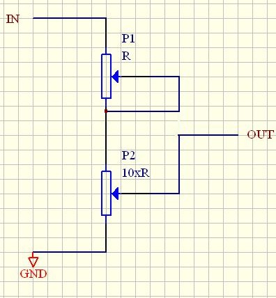
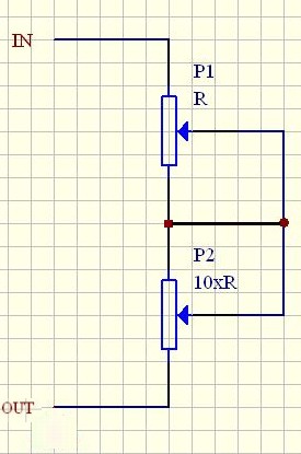
    At the author's request, I am starting a discussion on replacing impractical multiturn peers with "ordinary" potentiometers. Two each for current and voltage regulation. The purpose of this modification is to obtain fine and coarse adjustments. This makes quick, precise settings much easier.

    Both pictures come from our forum, source at the bottom.
    Tension:
    Set - DC / DC converter 9A XL4016 and panel meter DSN-VC288, assembly, test


    Electricity:
    Set - DC / DC converter 9A XL4016 and panel meter DSN-VC288, assembly, test

    Source.
  • #10
    eurotips
    Level 39  
    Coarse and fine adjustments are only needed for voltage adjustments.
    Additionally, the problem of linearity of this regulation (output voltage as a function of the angle of rotation of the potentiometer knob) has to be solved.
    For this purpose, the description of this converter should be supplemented with a table of relations between the potentiometer setting and the output voltage, then make a diagram of it.

    To use the entire 1.2-35V output voltage range, the most sensible solution would be to abandon the potentiometer adjustment in favor of a multi-position switch and select resistors. Then the scale would have a logical appearance, because whoever tried to do it for the potentiometer knows what I am writing about.
  • #11
    CMS
    Administrator of HydePark
    eurotips wrote:
    For this purpose, the description of this converter should be supplemented with a table of relations between the potentiometer setting and the output voltage, then make a diagram of it.


    No sense,. As a colleague imagines it in the CC mode. Such a scale would be appropriate only for a load with a specific current. See how it is made in factory power supplies.
  • #12
    Anonymous
    Anonymous  
  • #13
    CMS
    Administrator of HydePark
    Młody elektronik 13 wrote:
    Wait a minute! What is the purpose of creating setting tables, nonlinear scales


    Well, I said that it makes no sense :) .

    Whereas:

    Młody elektronik 13 wrote:
    PR and miracles


    This is a different story. As the settings are often changed to a large extent, the multiturn potentiometer is very inconvenient to use.
  • #14
    Anonymous
    Anonymous  
  • #15
    eurotips
    Level 39  
    Młody elektronik 13 wrote:
    Besides, expensive. I'm just in favor of PRs, I was a little carried away. I just wanted to cut it short unnecessary polemics and punching points :) How can you make a setting table for potentiometers when each potentiometer has slightly different parameters?


    It is true that in the set with a digital voltmeter the scale is not needed, I agree with that.

    However, the connection scheme itself requires improvement.
    The first thing to check is whether leaving the pin4 ground unconnected (photo from the first post) does not affect the ammeter indications? because I have already fought with this problem, in one panel, leaving this cable in the air distorted the indications by as much as 50%

    The second thing is there are two measuring shunts, on the converter module and on the panel. In practice, a panel shunt is enough, in the converter it should be desoldered and a cable connected to the panel shunt.
    The current indications will remain correct, typically the panel shunt is 0R005 and the inverter shunt is 0R01, so after such a change, the current limit setting should be corrected.
  • #16
    sylweksylwina
    Moderator of Computers service
    This set is great. I just have some 24V power supplies and I will use it and make a power supply for very lazy people :D
  • #17
    piterek-23
    Level 33  
    CMS wrote:
    At the author's request, I am starting a discussion on replacing impractical multiturn peers with "ordinary" potentiometers. Two each for current and voltage regulation. The purpose of this modification is to obtain fine and coarse adjustments. This makes quick, precise settings much easier.

    Both pictures come from our forum, source at the bottom.
    Tension:
    Set - DC / DC converter 9A XL4016 and panel meter DSN-VC288, assembly, test


    Electricity:
    Set - DC / DC converter 9A XL4016 and panel meter DSN-VC288, assembly, test

    Source.

    Have you done any inverter modification? How do the potentiometers work? ;)
  • #18
    CMS
    Administrator of HydePark
    Not this one, but I have already used this solution and it works as it should. You can even see them in several of my articles.
  • #19
    huluk
    Level 32  
    Quote:
    As the settings are often changed to a large extent, the multiturn potentiometer is very inconvenient to use.


    In such cases, if I often use several voltages interchangeably, I prepare appropriate dividers and select with switches, whether I need one of the previously "programmed" or full manual control. It also increases the durability of the potentiometer - you don't have to turn it so often :)
  • #20
    piterek-23
    Level 33  
    This is what happened to me ... is it a good idea to make a workshop power supply on this converter, and use a switching power supply as a power supply?
    I need a power supply mainly to play with microcontrollers etc.
    I am asking because everyone builds their workshop power supplies on a transformer ;)
  • #21
    TechEkspert
    Editor
    For microcontrollers and systems with microcontrollers, a better solution may be a power supply with several fixed output voltages, eg 3.3V, 5V, 12V. At lower output currents, they can even be linear stabilizers.

    An adjustable converter made of material will be useful where smooth regulation of the output voltage is needed,
    using a recycled switching power supply as a power source can reduce construction costs.
  • #22
    piterek-23
    Level 33  
    TechEkspert wrote:
    For microcontrollers and systems with microcontrollers, a better solution may be a power supply with several fixed output voltages, e.g. 3.3V, 5V, 12V

    I didn't think about it - really constant voltages such as 3V3 and 5V would also be useful ;)
    TechEkspert wrote:
    An adjustable converter made of material will be useful where smooth regulation of the output voltage is needed,

    I am thinking of a universal workshop power supply, but fully impulse.
    The regulation will be useful for testing systems powered by batteries, accumulators - discharge simulation.
    TechEkspert wrote:
    using a recycled switching power supply as a power source can reduce construction costs.

    I have an AC / DC 230V 24V 6A converter module and hence these questions / combinations ;)
  • #23
    TechEkspert
    Editor
    I think that in your case you can use:
    - AC / DC 230V 24V 6A: as a power source
    - DC / DC 9A XL4016 + DSN-VC288 as part of a regulated power supply
    - for low power receivers several 3.3V, 5V, 12V linear stabilizers (here the 24V is a bit unfavorable, perhaps preceded by DC / DC: https://www.elektroda.pl/rtvforum/viewtopic.php?p=16995581#16995581)
    - for low-power constant voltages but with an insulated GND, AIMTEC converters can be useful

    With time, you can add the current measurement in 3.3 / 5 / 12V branches
  • #24
    piterek-23
    Level 33  
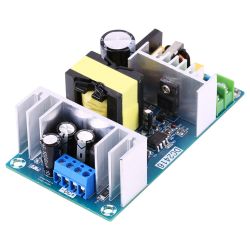
    My power source:
    Set - DC / DC converter 9A XL4016 and panel meter DSN-VC288, assembly, test
    [syntax=text]
    AC-DC Switching Power Supply Module AC 100-240V to DC 24V 9A Power Supply Board
    Feature:
    Input voltage: AC 100-240V 50/60HZ
    Output voltage: DC 24V
    Output current: 6-9A
    Output power: 150W(Max 220W)
    Location pore size: 105.8 x 55.7mm
    Overall dimensions: 115 x 65mm
    Ripple noise:
  • #25
    Anonymous
    Anonymous  
  • #26
    Dżyszla
    Level 42  
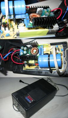
    So I put it together. The basis is the AC / DC 24V / 4A switching power supply. And then the converter in question.
    The measuring module is very similar, but a bit different - there, the power supply is on one plug (and it is connected directly to the AC / DC output, i.e. 24V), and the measurements on the other - 3-pin.

    Behind the power supply and an additional 1000?F / 63V capacitor at the input of the converter, both modules would not fall into some strange resonance. Although I am wondering if I would not put a tiny resistor in series, however, because a terribly high current goes to the capacitor when it is turned on.

    The power supply has aluminum heat sinks, which have also become a frame for the converter after using a piece of aluminum and a drill.

    Everything is closed in a fairly large housing, which was used by me for the current 14V / 1A + 5V / 1A transformer power supply (it broke down), hence the holes and scale on the front panel (going somewhere to get a clean panel?). All that's left is to desolder the potentiometers and mount them on the panel. At the beginning I was thinking about a multiturn, but what @ piterek-23 wrote convinced me and for voltage regulation I will use his idea on ordinary potentiometers. I will only use one for the electricity.

    Eventually I'll have a fast phone charger at home :) With this load of 5V / 0.9A, the whole thing is barely warm. However, I am saddened by the fact that the idle power consumption is as much as 2W (mainly the fault of the AC / DC module).

    PS. Measurement under load (with a laptop) - 20V / 1A (20W), power consumption 24W, i.e. the loss is approx. 4W. The instantaneous load jumped to 1.7A and holds 20.0-20.1V beautifully all the time (according to the digital meter). At 2A (40W) the voltage drops a bit (19.9V) and the current consumption is 47W. I do not have an oscilloscope at hand, but I will check the waveform in such conditions one day.

    Set - DC / DC converter 9A XL4016 and panel meter DSN-VC288, assembly, test
  • #27
    CMS
    Administrator of HydePark
    Dżyszla wrote:
    and the power consumed is 47W.


    A colleague is sure of this ;) .
  • #28
    Dżyszla
    Level 42  
    Yes. A total of 7W was lost. Of course, it's also just a rough measurement, so you can count 5% here, 5% there ... But is that something impossible?
  • #29
    CMS
    Administrator of HydePark
    I meant more about "POWER DOWNLOAD" :D .
  • #30
    Dżyszla
    Level 42  
    AND :) Colloquial speech :) Of course: power :)