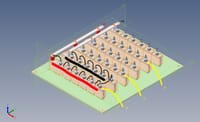
Hello everyone,So I have been given a project at work here to try and design a 12.5Kv AC-DC rectifier for a new customer. This is somewhat out of our typical range as we normally only work with low voltage assemblies rather than medium voltage, but it's not entirely beyond our capacity to design.What I'm hoping someone can help me with is the required creepage distances needed. Attached is a screenshot taken of a preliminary design I have in my head. Each diode is of an avalanche type with a PIV of 5Kv, anode to stud. With 6 in series between each AC and DC point this should give us a total rating of 30Kv which falls in line with our standard practice of doubling the required PIV of the rectifier, minimum.Now I understand the need for the large creepage distance between each 'limb' of the rectifier as this is where we will see the largest difference in voltage potential, but am I right to assume that because the voltage potential between each heatsink in a single limb is ~0.7v, can I design this assembly to have a creepage and clearance between each heatsink to suit that 0.7v? Or will I need to design the full creepage and clearance between ALL heatsinks to suit 12.5Kv?Normally I wouldn't even question my logic here, but another of our design engineers isn't so sure and has planted a seed of doubt in my head.For reference purposes, the material these heatsinks are being mounted to is FR4, which according to our supplier has a CTI of 300, placing it in insulating material group IIIa.With regards to the attached image, forgive my MS Paint skills but I've tried to show where the diodes will connect to each heatsink and relevant connection points for the AC and DC.If you need more information to help me out, let me know and I'll try to help.


