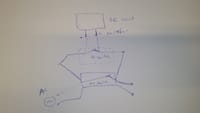
Hi All,Many thanks for answer my questions. I am sorry that my initial description is not clear enough.I am trying to explain again:1) Initial DC circuit (5V) , has 2 connector (+ and -) as you can see as the picture. That works as a jumper between the two ( you can think of as a computer main-board jumper). To make the circuit do something, I need to connect this two connectors by a simple wire or jumper, which I call a switch. The DC circuit is also powered by a standard AC power, then convert to DC as in PC computer.
2) I have successfully connected and controlled by a DC switch, the DC switch circuit operating at DC 5V source. The power supply for the DC circuit is a standard AC power (220 V). I can turn on and off the switch. This means when I turn on the DC switch, my DC circuit work as I expected.
3) Now I would like to add another AC smart switch (parallel to the DC switch). This switch works as follows: when it is turned on, the wire of the left side is connected to the wire on the right side. The smart switch means just Wifi enable switch, which I can control remotely. The switch seems to me mechanical of some sort, as I hear a sound when I turn it on.As you can see from the picture, I did not fully connect the two output wires of the AC switch to the DC circuit. I only hijack of one wire of it to connect + and -.
I think that (maybe I am wrong) because I did not connect two output wires of the AC switch to the DC circuit, I suppose not AC coming to my DC circuit as not closed circuit. However I am not sure about this. For example: this link
https://electrical-engineering-portal.com/using-ac-and-dc-together-in-electrical-system.
Obviously for this to work I need to connect both DC switch and AC switch to the two connector (+ and -) otherwise how is that possible? Many thanks for your help, John
PS: the application is household heating. If you are interested I can explain more.


