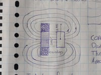
i'm trying to design a certain type of bicycle dynamo to light an LED on my bike. I'm trying to build something similar to what the company reelight sells: https://www.reelight.com/collections/bike-lights/products/cph?variant=5764959109147It uses a magnet on the bicycle wheel to induce a current in a a coil to drive an LED. Since I want the LED to stay on during the time when no current is induced in the coil I have come up with the design attached. Please correct me if I have made a mistake. I am not an electrical engineer, but I want to learn the basics. I want to calculate the amount of windings necessary to deliver a proper voltage to drive the LED. Also, a large enough power has to be generated when current is induced to drive the LED for the time when no current is induced. Following are all the fixed parameters:- Magnet thickness: 5 mm- Magnet diameter: 10 mm- Distance magnet-coil: 5 mm- Magnetic field strength @5 mm: 323-430 Gs (calculated here: https://www.kjmagnetics.com/calculator.asp?calcType=disc)- LED current: 20 mA- Coil core diameter: 10 mm- Core permeability: ? (unsure)- minimum magnet speed relative to coil: 2 m/sThe orientation of the magnet relative to the coil can be seen in the second attachment. Now i'm trying to figure out how many windings I should use for the coil. For that I tried using the formula for magnetic induction: EMF = -N(dPhi/dt) , but that does not get me anywhere since i'm not sure what to fill in for d Phi and dt. Also, i'm not sure how to proceed from here. What influence does the coil resistance (yet to be determined by wire diameter and windings) have on the current flowing to the capacitor? Could someone help me with this? Thanks so much!


