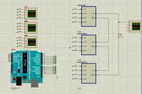
https://drive.google.com/open?id=1ItHTf4ONYHiTsEritgMxgIs1IusnLgxV
I made 7-level proteus simulation, using signal control arduino code. It's not simulating, I try to Debug it using Digital Analyzer for H-Bridge (sub-circuit), and noted that signal from arduino is not passing through octocoupler, and thus gate is not triggering (see sub image).
When I try to simulate High and Low side of bridge (see images), it works fine; but the whole is not working.
Can anyone solve this????


